Method and arrangement for discharging an energy storage system for electrical energy

a technology of energy storage system and energy storage system, which is applied in the direction of engine-driven generators, electric devices, process and machine control, etc., can solve the problems of a few minutes of discharge process, no safe rescue operation, and potential hazards to rescue teams or other assisting persons

Active Publication Date: 2010-02-04
VOLVO LASTVAGNAR AB
View PDF5 Cites 26 Cited by
  • Summary
  • Abstract
  • Description
  • Claims
  • Application Information

AI Technical Summary

Benefits of technology

[0015]Preferably, the trigger signal is transmitted by an accident sensing sensor or such system like an anti-collision detection system. The accident sensing sensor, or system, can be a sensor for realizing an accident the moment it happens, correlating the initialization of the discharge process for example to an airbag deployment signal, or an accident prediction sensor calculating the probability of an accident and transmitting the trigger signal in case the probability exceeds a certain threshold. Both solutions have the main advantage that the discharge is already in process when the rescue team arrives or is, in case of the accident prediction sensor, or system, already completed or almost completed.
[0016]It is further advantageous to provide a signal possibility signaling the status of the discharge process, i.e. that the discharge of the energy storage system is completed, or is still in process and / or still needs to be initiated and performed.

Problems solved by technology

In case such a hybrid vehicle is involved in an accident there is a potential hazard to a rescue team or other assisting persons or to the driver and the passengers themselves due to the high voltage of the energy stored in the energy storage system.
Disadvantageously, the use of a large resistance for the discharge resistor or the use of the two discharge methods described above (even if they are performed in parallel) means that the discharge process takes several minutes before it is completed.
During that time no safe rescue operation can be performed which might even cost a person's life.
Releasing the coolant results in a sudden drop of temperature of the storage unit.

Method used


Image

  • Method and arrangement for discharging an energy storage system for electrical energy
  • Method and arrangement for discharging an energy storage system for electrical energy
  • Method and arrangement for discharging an energy storage system for electrical energy

Examples


Embodiment Construction

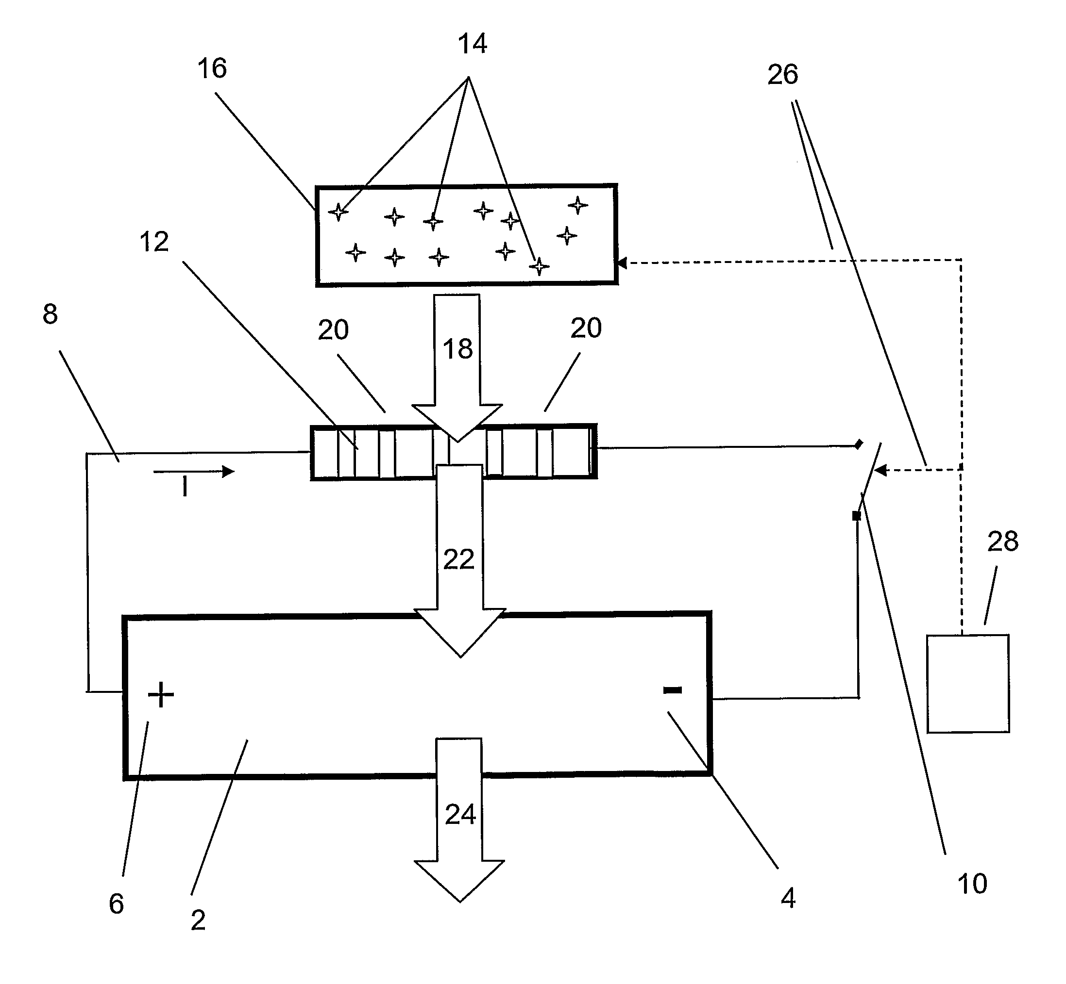
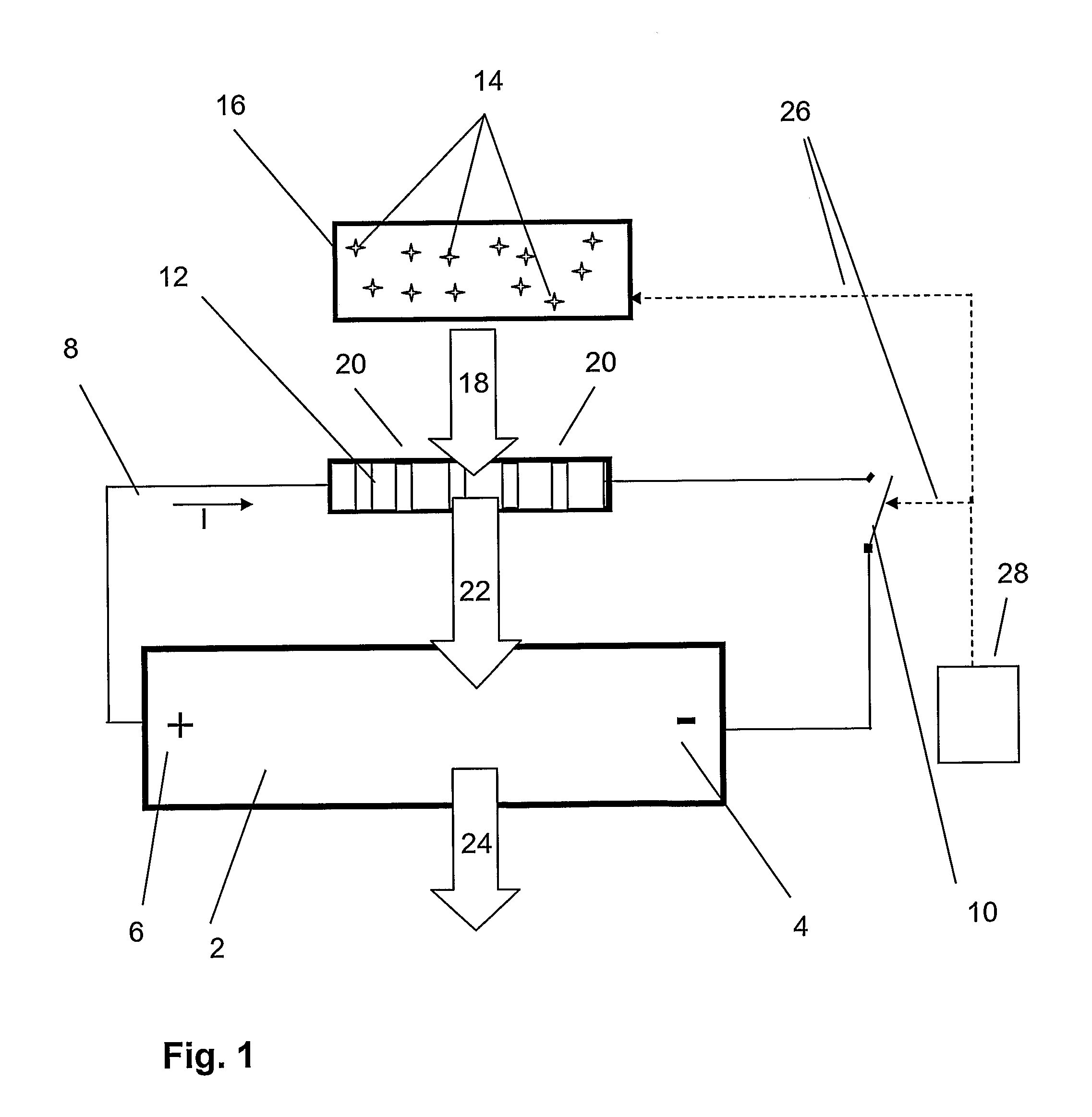
[0022]FIG. 1 shows schematically a first preferred embodiment of the inventive arrangement. An energy storage system 2 stores electric energy produced by a fuel cell or a generator (not shown) and is designed for high voltages. Such a high voltage energy storage system stores energy in the range of typically several hundreds volts in contrast to a “normal” vehicle battery providing electric energy at voltage levels of 12 V or 24 V. The energy storage system 2 can comprise a plurality of capacitors or batteries connected in series having a minus pole 4 and a plus pole 6. FIG. 1 shows only a single capacitor or battery for the sake of simplicity.

[0023]In case of an accident, the energy storage system 2 is a potential hazard to a rescue team or other assisting persons or to the passengers of the vehicle due to the high voltage of the system. In such situations it is therefore necessary to discharge the energy storage system 2 as fast as possible to zero or to a safe level.

[0024]For dis...


PUM


Abstract

A method and an arrangement for discharging an energy storage system for electrical energy, particularly in a vehicle having a hybrid drive line, by means of a first discharge resistor, wherein a coolant such as carbon dioxide gas is provided to the first discharge resistor during discharge of the energy storage system for leading off heat as well as a hybrid vehicle comprising such an arrangement.

Description

BACKGROUND AND SUMMARY[0001]The present invention relates to a method and an arrangement for discharging an energy storage system for electrical energy, particularly in a vehicle having a hybrid drive line (hereinafter referred to as “hybrid vehicle”), by means of a discharge resistor as well as to a hybrid vehicle comprising such an arrangement.[0002]In the following the invention is described in connection with hybrid vehicles. However, the invention is not limited to this application. For instance, it can be also used in stationary power generation systems comprising such an energy storage system. The invention is also applicable to stationary and / or movable construction equipments such as construction vehicles or off road machines.[0003]Hybrid vehicles in general comprise at least two drive engines, wherein a traditional combustion engine is most frequently supported by an additional electrical drive unit. The electric energy for running the electric drive unit is commonly provi...

Claims


Application Information

Patent Timeline
Patent Type & Authority Applications(United States)
IPC IPC(8): H02J7/00H05K7/20H01C1/08G08B21/02
CPCB60L3/0046Y02T10/70B60L3/0069B60L3/04B60L11/005B60L11/14B60L11/1874B60L11/1887B60L2250/10Y02T10/7022Y02T10/705Y02T10/7077Y02T10/84Y02T90/34B60L3/0007B60L3/0053H01M10/44H01M10/441B60L50/40B60L50/16B60L58/26B60L58/40B60L58/10Y02T10/7072Y02E60/10G05B9/02Y02T90/40
Inventor FORSLOW, DANIEL
Owner VOLVO LASTVAGNAR AB
Why Eureka
Try Eureka