
Stabilized near-infrared laser

a near-infrared laser and stable technology, applied in the direction of laser details, active medium shape and construction, electrical equipment, etc., can solve the problems of unstable mode-hopping mode operation, change in the effective optical length of the resonator, etc., to minimize the effect of mode-hopping

Inactive Publication Date: 2010-02-04
COHERENT INC
View PDF73 Cites 15 Cited by
  • Summary
  • Abstract
  • Description
  • Claims
  • Application Information

AI Technical Summary

Benefits of technology

[0007]The present invention is directed to minimizing mode-hopping in a CW single-longitudinal-mode laser. In one aspect, a laser in accordance with the present invention comprises a laser resonator configured for operation in a single longitudinal mode. At least one gain-element is located in the laser-resonator. An arrangement is provided for energizing the gain-element such that continuous-wave (CW) single-longitudinal-mode radiation circulates in the resonator, the circulating radiation having a fundamental wavelength within a gain-bandwidth of the gain-element. An optically nonlinear crystal is also located in the resonator. The resonator is further configured such that a fraction of the circulating CW single-longitudinal-mode radiation is delivered from the resonator as output radiation at the fundamental wavelength. A fraction of the circulating radiation in the resonator is converted by the optically non-linear crystal into second-harmonic radiation for minimizing mode-hopping in the CW single-longitudinal-mode output radiation of the resonator.

Problems solved by technology

In practice, changes in the operating environment or parameters of the resonator, particularly changes in temperature, will cause changes in the effective optical length of the resonator.
However stably a resonator is operating before a mode-hop occurs, there is a period of unstable multi-mode operation that accompanies the mode hop.
Even with all reasonable precautions being taken to stabilize the operating environment of the resonator such mode-hops can occur at irregular intervals of a few seconds or minutes, possibly at inconvenient moments.

Method used


Image

  • Stabilized near-infrared laser
  • Stabilized near-infrared laser
  • Stabilized near-infrared laser

Examples


Embodiment Construction

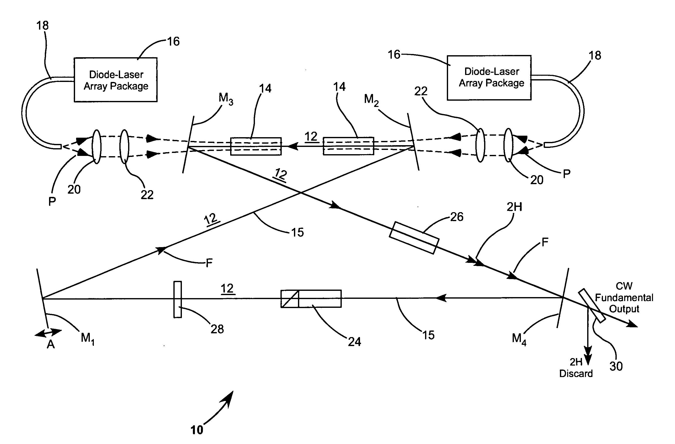
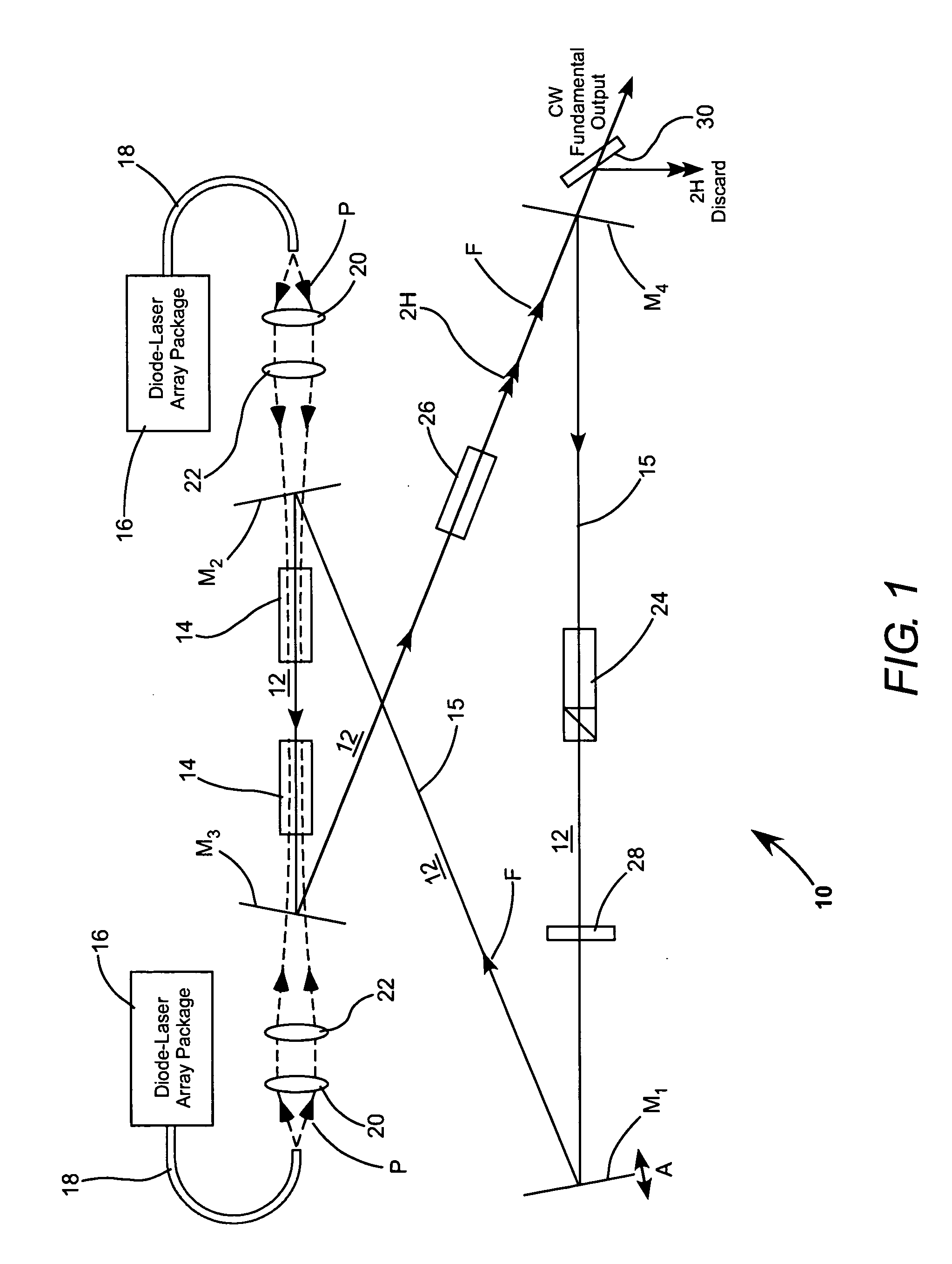
[0013]Referring now to the drawings, wherein like components are designated by like reference numerals, FIG. 1 schematically illustrates an intracavity-frequency-doubled ring-laser 10 including a preferred embodiment of the pumping method of the present invention. Laser 10 includes a ring resonator 12 in a configuration commonly referred to by practitioners of the art as a “bow-tie” configuration. Resonator 12 is formed by mirrors M1, M2, M3, and M4. Two solid state gain-elements 14, for example gain-elements of Nd:YVO4, are included in the resonator between mirrors M2 and M3.

[0014]Each gain-element 14 is continuous-wave (CW) optically pumped by a beam of pump-light P from a corresponding diode-laser fiber-array package (diode-laser FAP) 16. The pump-light is delivered from each of the diode-laser FAPs via a fiber bundle or a multi-mode transport fiber 18. Light from the transport fiber is collimated by a lens 20 and focused by a lens 22 to a beam-waist in the corresponding gain-ele...


PUM


Abstract

A traveling wave ring-resonator is configured to deliver CW single-longitudinal-mode radiation having a fundamental wavelength characteristic of an optically pumped gain-element in the resonator. The delivered fundamental-wavelength radiation is the output-radiation of the resonator. An optically nonlinear crystal is located in the resonator and arranged to convert a fraction of fundamental-wavelength radiation into second harmonic radiation. The conversion of this fraction of fundamental-wavelength radiation to second-harmonic radiation minimizes mode-hopping in the output radiation.

Description

TECHNICAL FIELD OF THE INVENTION[0001]The present invention relates in general to solid state lasers. The invention relates in particular to solid-state lasers arranged to operate in a single longitudinal mode.DISCUSSION OF BACKGROUND ART[0002]A laser having a laser resonator that operates in a single longitudinal mode is preferred in applications where low bandwidth, high temporal coherence, and low noise are required. Such applications include high-resolution spectroscopy, optical parametric oscillator OPO pumping, and interferometry, among others. In a relatively long resonator for example a resonator having a length of about 1.0 meters, there are approximately 885 possible longitudinal modes of oscillation per nanometer of wavelength at 1064 nm, spaced equally in frequency. The resonator can be regarded as a very thick etalon with the possible modes being equivalent to transmission wavelengths of that etalon and the frequency spacing of adjacent modes being equal to the free spe...

Claims


Application Information

Patent Timeline
Patent Type & Authority Applications(United States)
IPC IPC(8): H01S3/10
CPCH01S3/07H01S3/08031H01S3/0816H01S3/083H01S3/1673H01S3/105H01S3/109H01S3/137H01S3/09415
Inventor MURDOCH, KEITH M.
Owner COHERENT INC
Learn More