Method and System for Coupling Multimode Optical Fiber to an Optical Detector

a multi-mode optical fiber and optical detector technology, applied in the field of multi-mode optical fiber coupling to optical detectors, can solve the problems of unstable signals received from optical detectors, multi-mode pigtails, and insufficient alignment of conventional manufacturing methods, and achieve stable output effects

Active Publication Date: 2010-02-04
CORNING OPTICAL COMM WIRELESS
View PDF31 Cites 14 Cited by
  • Summary
  • Abstract
  • Description
  • Claims
  • Application Information

AI Technical Summary

Benefits of technology

[0016]According to a further aspect of the present invention, is to provide a method for manufacturing an optical detector subassembly having a multimode optical fiber pigtail aligned to an optical detector that more consistently produces optical detector subassemblies that provide stable output while the optical fiber is manipulated.

Problems solved by technology

It has been discovered that while the single mode pigtail connected to the transmitter laser diode can be connected to the multimode optical fiber that is connected to the photodiode optical detector of the receiver, the multimode pigtail that is fixed to optical detector using conventional manufacturing methods may not be sufficiently aligned such that the signals received from the optical detector are not stable and are sensitive to movements of the multimode optical fiber.

Method used


Image

  • Method and System for Coupling Multimode Optical Fiber to an Optical Detector
  • Method and System for Coupling Multimode Optical Fiber to an Optical Detector
  • Method and System for Coupling Multimode Optical Fiber to an Optical Detector

Examples


Embodiment Construction

[0022]Reference will now be made in detail to embodiments of the present invention, examples of which are illustrated in the accompanying drawings, wherein like reference numerals refer to the like elements throughout. The embodiments are described below to explain the present invention by referring to the figures.

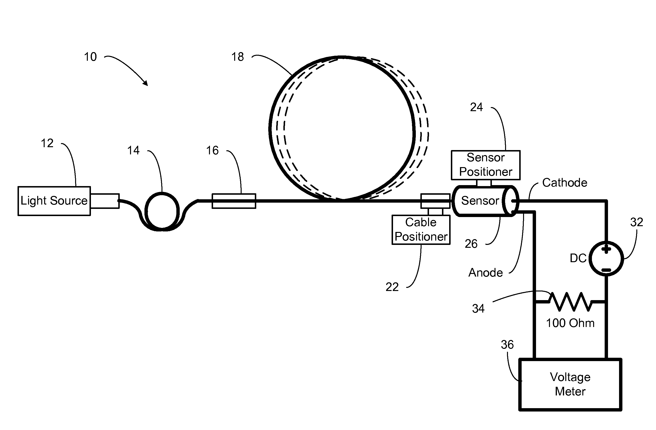
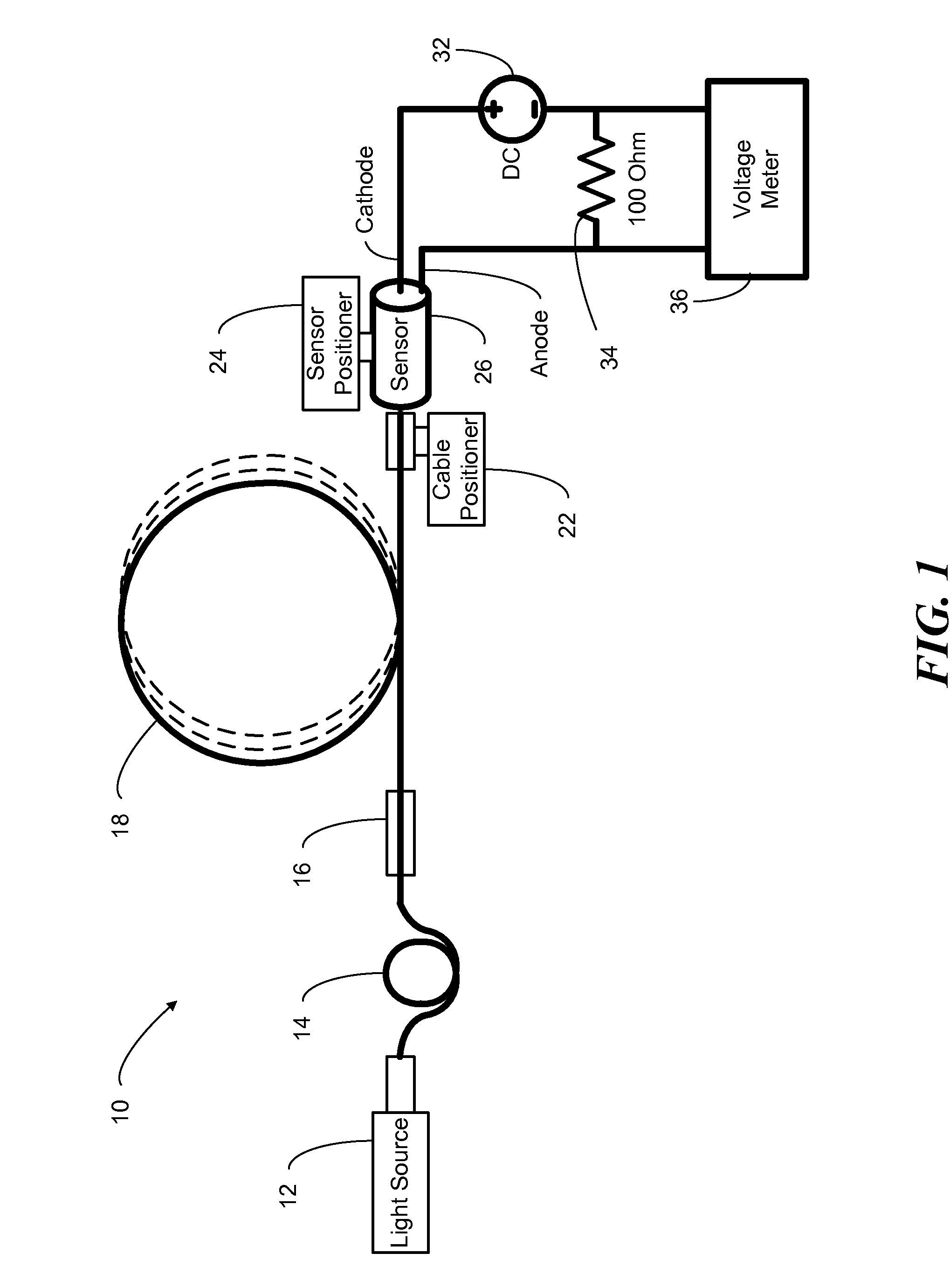
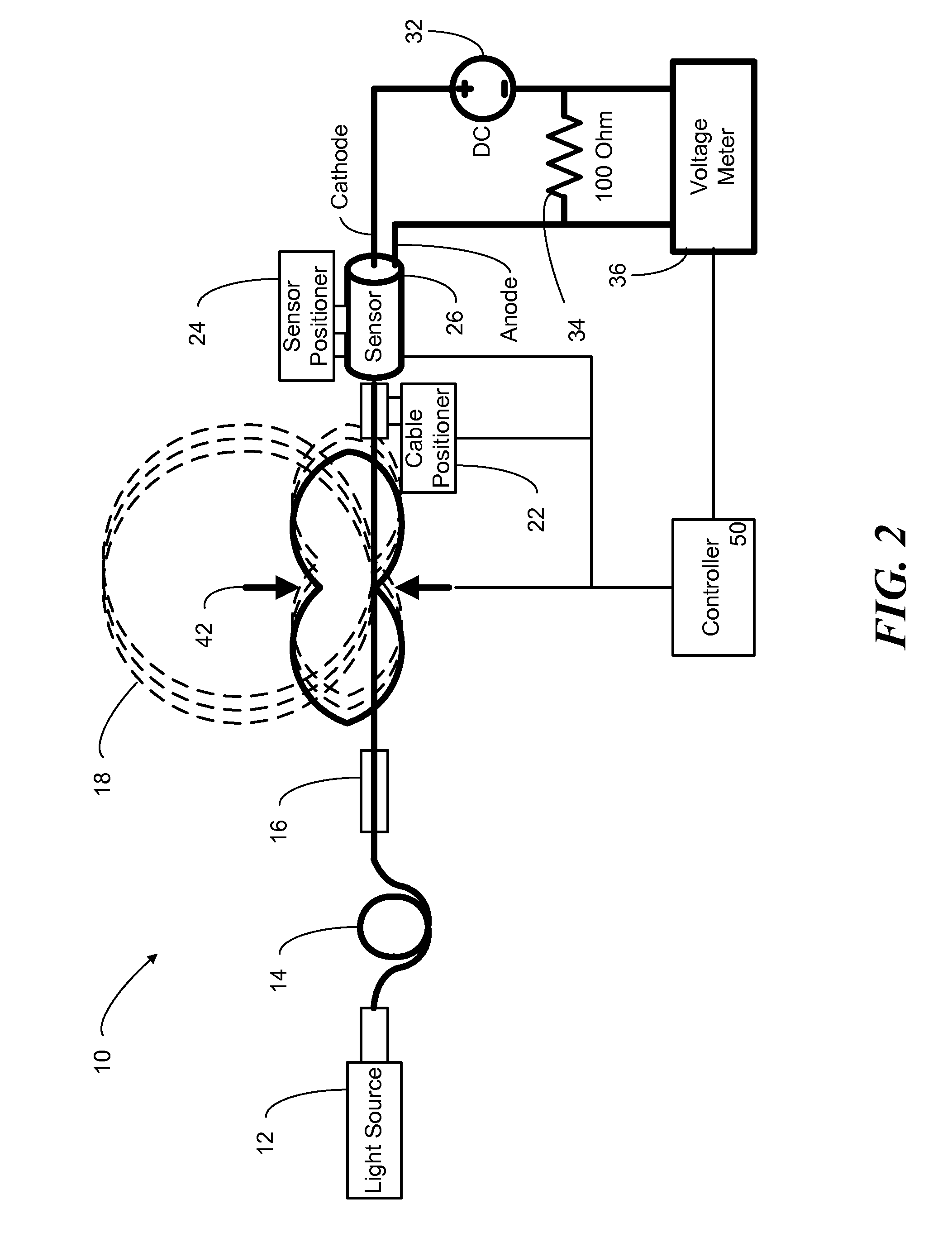
[0023]Referring now to the drawings, FIGS. 1 and 2 show a simplified diagram of a photodiode coupling system 10, according to an embodiment of the present invention. System 10 includes a light source 12 (for example, a Fabry-Perot laser diode) coupled, at its output, to an optical fiber pigtail 14. Optical fiber pigtail 14 is preferably a single mode optical fiber designed to carry the wavelength of light energy produced by light source 12. Optical fiber pigtail 14 can be coupled by a mating sleeve 16 to a multimode optical fiber 18. Optical fiber 18 can be wound into a coil of one or more loops of less than ten inches in diameter. The fiber terminations of optical fiber p...


PUM

PropertyMeasurementUnit
diameteraaaaaaaaaa
thresholdaaaaaaaaaa
frequenciesaaaaaaaaaa

Abstract

A method for making a multimode fiber optic subassembly includes alignment of an optical detector with a fiber termination of an optical fiber. The output of the optical detector (e.g. photocurrent) can be measured from light being transmitted through the optical fiber and detected by the optical detector. The end of the optical fiber and/or the optical detector can be positioned and angularly oriented in order to obtain relative maximum or peak output of the optical detector for a given position and orientation. The output of the optical detector can be monitored while mechanically manipulating, e.g. bending, flexing, shaking and/or twisting, the optical fiber, in order to verify that the positional relationship between the end of the optical fiber and the optical detector corresponds to a position and/or orientation that provides stable output from the optical detector. If the optical detector output is not stable, the end of the multimode optical fiber and the optical detector can be moved, changing the position and/or the orientation of one or both, until the output of the optical detector is stable during manipulation. If the optical detector output is stable, the end of the multimode optical fiber is fixed to the optical detector. The resulting subassembly, a fiber optic pigtail, can be made by cutting the optical fiber a short distance from the optical detector.

Description

CROSS-REFERENCE TO RELATED APPLICATIONS[0001]This application claims any and all benefits as provided by law of U.S. Provisional Application No. 61 / 084,659 filed 30 Jul. 2008, which is hereby incorporated by reference in its entirety.STATEMENT REGARDING FEDERALLY SPONSORED RESEARCH[0002]Not ApplicableREFERENCE TO MICROFICHE APPENDIX[0003]Not ApplicableBACKGROUND[0004]1. Technical Field of the Invention[0005]The present invention relates to a method and system for coupling multimode optical fibers to optical detectors. The present invention also relates to fiber optic pigtails made in accordance with the inventive method.[0006]2. Description of the Prior Art[0007]Fiber optic communication devices include a transmitter that comprises an optical energy source such as a laser diode coupled to one end of an optical fiber and a receiver that comprises an optical sensor or detector coupled to the other end of the optical fiber. The transmitter emits signal that are carried over the optical...

Claims


Application Information

Patent Timeline
Patent Type & Authority Applications(United States)
IPC IPC(8): G02B6/42H05K13/00
CPCG02B6/4225Y10T29/49002G02B6/4227
Inventor SHAPIRO, CARMI
Owner CORNING OPTICAL COMM WIRELESS
Why Eureka
Try Eureka