Metal separator for fuel cell and fuel cell stack having the same

a technology of fuel cell and metal separator, which is applied in the direction of cell components, sustainable manufacturing/processing, and final product manufacturing, etc., can solve the problems of reducing the durability of the electrolyte membrane, difficult to individually form a passage of coolant, and generating a lot of heat, so as to reduce the manufacturing time and cost of the metal separator, improve the cooling performance without increasing the thickness, area and volume, and improve the effect of cooling performan

Active Publication Date: 2010-02-04
HYUNDAE STEEL CO LTD
View PDF6 Cites 20 Cited by
  • Summary
  • Abstract
  • Description
  • Claims
  • Application Information

AI Technical Summary

Benefits of technology

[0042]In accordance with the present invention, the metal separator and the fuel cell stack having the same can improve the cooling performance, by including the coolant channel connection portion for enabling the coolant to flow between the parts of the coolant channel or between the coolant channels.
[0043]In accordance with the present invention, the metal separator and the fuel cell stack having the same can improve the cooling performance without increasing the thickness, area and volume of the separator, by forming the coolant channel connection portion by the stepped portion provided at the reaction gas channel.
[0044]In accordance with the present invention, the metal separator and the fuel cell stack having the same can reduce the manufacturing time and cost of the metal separator, by forming the coolant channel connection portion on the metal separator by a general stamping process.
[0045]In accordance with the present invention, the metal separator and the fuel cell stack having the same can improve the cooling efficiency, by intensively cooling the active heat generation part by controlling the amount of the coolant introduced into the coolant channel.
[0046]In accordance with the present invention, the metal separator and the fuel cell stack having the same can reduce a pressure drop amount by lowering flow resistance of the reaction gas, by including the structure of preventing deformation of the space to / from which the reaction gas is introduced and discharged.
[0047]In accordance with the present invention, the metal separator and the fuel cell stack having the same can improve stability and efficiency of the fuel cell system, by increasing airtightness by double sealing of the coolant portion and the reaction gas portion.

Problems solved by technology

When a reaction occurs in the fuel cell, a lot of heat is generated due to an activation loss, deoxidization at the cathode, and Joule heating.
If the electrolyte membrane is exposed to a high temperature for a long time, durability of the electrolyte membrane decreases.
It is thus difficult to individually form a passage of a coolant.
Furthermore, the coolant channel is narrow and crooked, so that the coolant cannot smoothly flow in or out.
Nevertheless, the coolant does not flow well into the middle portion of the separator accumulating a lot of heat.
In addition, the buffering region increases the size of the separator.
However, a high density of metal increases a weight of a stack.
As a plurality of separators overlap with each other, the production cost also increases.
However, it increases the cost and causes the structural difficulty in stack lamination.
However, in the case of a metal separator manufactured by thin plate molding, a pre-determined fastening pressure deforms part of the metal separator as well as the gasket.
Such deformation interrupts inflow of the reaction gas and the coolant, and thus applies many loads to peripheral devices, particularly, to a blower or a pump.
As a result, efficiency of the system is reduced.
However, the gasket cannot completely support compression by a load.
As it is difficult to mount one metal separator on the other, a manufacturing process of the metal separator is complicated.
Furthermore, the added metal plate increases a weight of a stack, thereby applying many loads to a fuel cell system mounted apparatus.

Method used


Image

  • Metal separator for fuel cell and fuel cell stack having the same
  • Metal separator for fuel cell and fuel cell stack having the same
  • Metal separator for fuel cell and fuel cell stack having the same

Examples


Embodiment Construction

[0057]A metal separator for a fuel cell and a fuel cell stack having the same in accordance with the preferred embodiments of the present invention will now be described in detail with reference to the accompanying drawings.

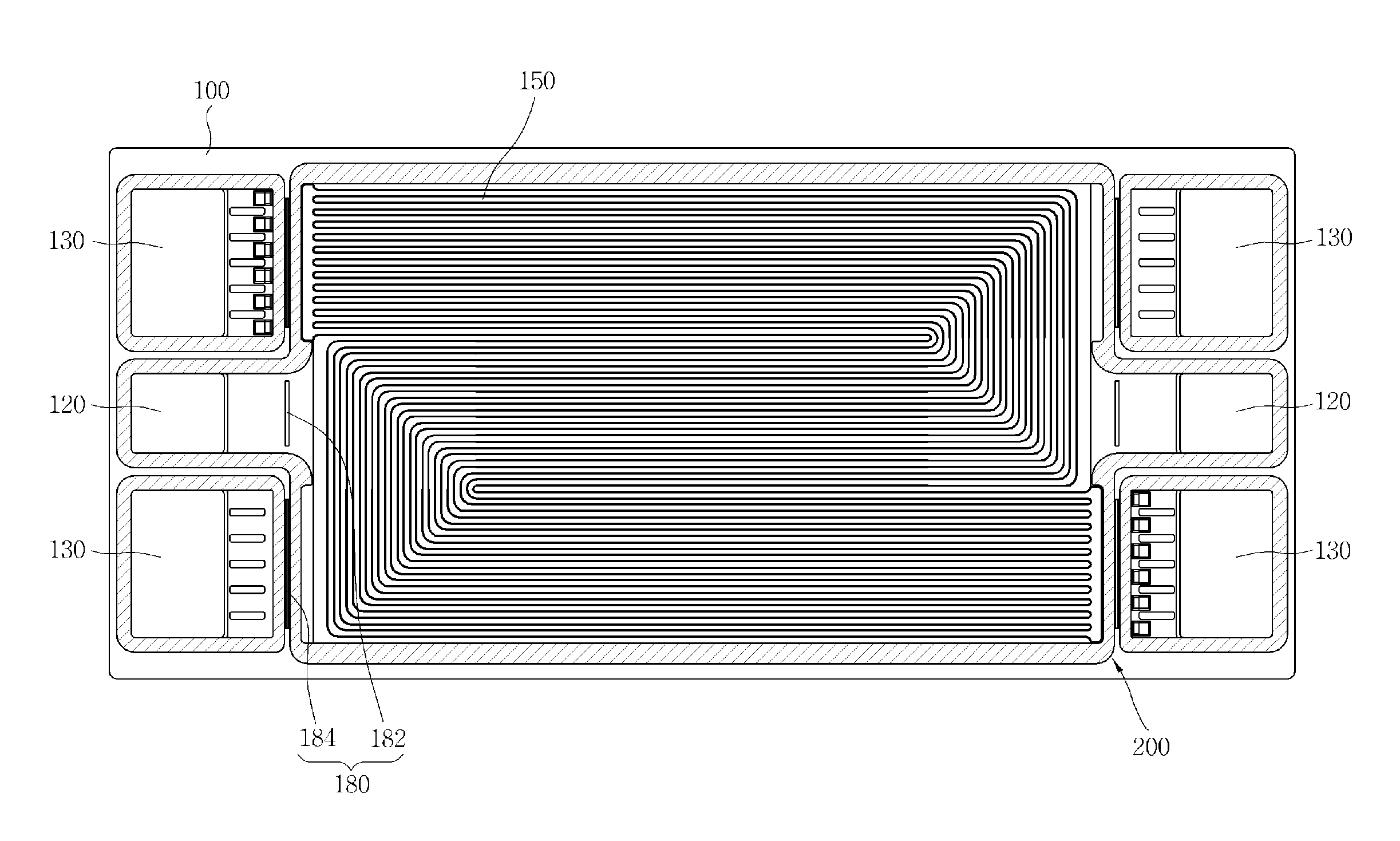
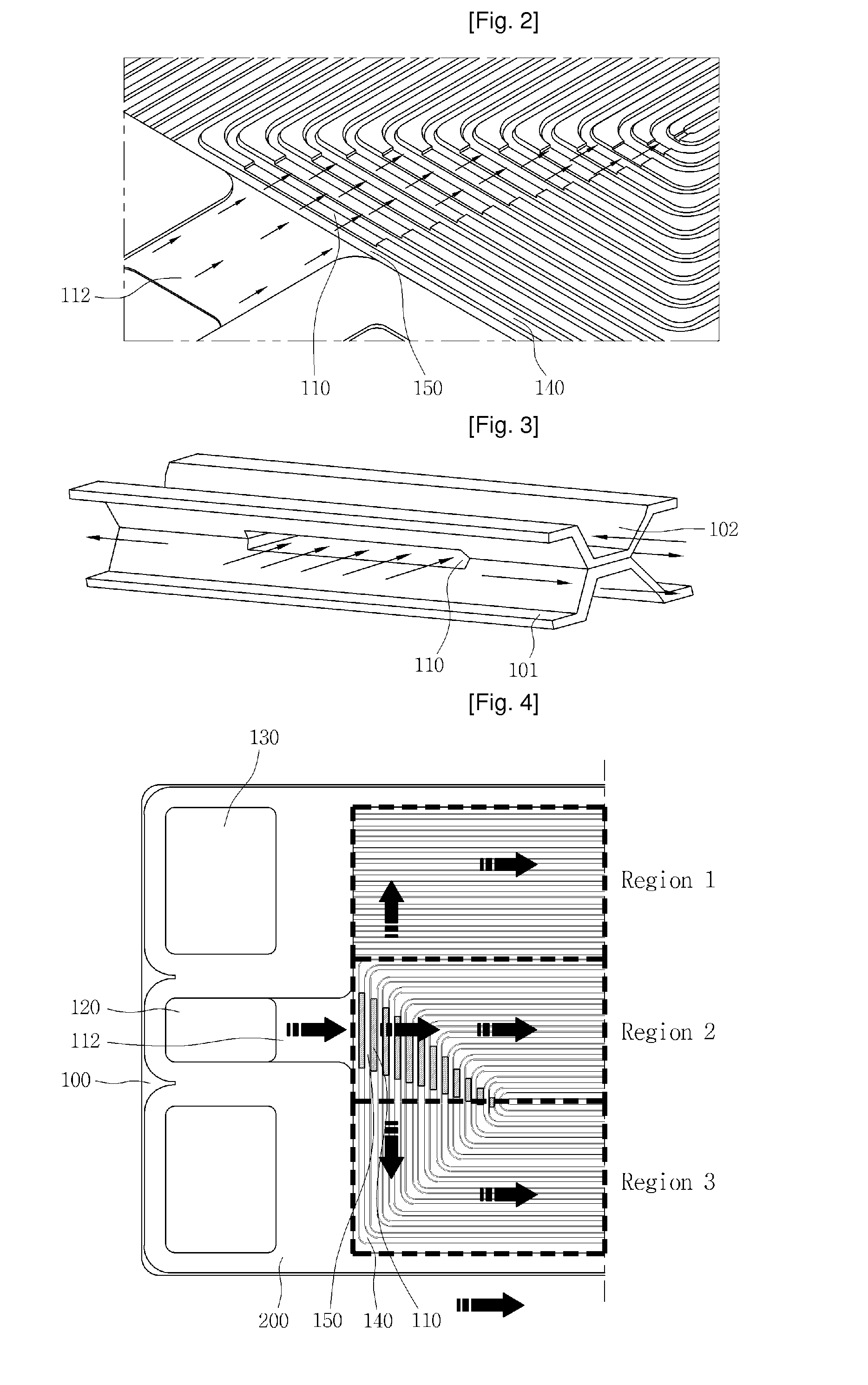
[0058]FIGS. 1 and 2 are views illustrating a separator in accordance with a preferred embodiment of the present invention. The metal separator 100 includes a reaction gas manifold 130, a coolant manifold 120, a reaction gas channel 140, a coolant channel 150, a coolant channel connection portion 110, and a coolant channel connection path 112. In addition, a gasket 200 is adhered to the metal separator 100 so as to prevent leakage of a reaction gas and a coolant from the metal separator 100. The reaction gas manifold 130 serves to supply a reaction gas to the metal separator 100. Generally, the reaction gas manifold 130 is positioned at one side of the metal separator 100. The reaction gas introduced into the metal separator 100 through the reaction gas manifold 1...


PUM

PropertyMeasurementUnit
structureaaaaaaaaaa
widthaaaaaaaaaa
hardnessaaaaaaaaaa

Abstract

The present invention discloses a metal separator for a fuel cell including a reaction gas channel formed to protrude from a first face of the metal separator to a second face thereof, a coolant channel formed between the reaction gas channels protruding from the second face of the metal separator, a reaction gas manifold opened to introduce a reaction gas into the metal separator, a coolant manifold opened to introduce a coolant into the metal separator, and a stepped portion positioned at any one of the space between the reaction gas channel and the reaction gas manifold, and the reaction gas channel. This configuration serves to widen the reaction gas flowing portion and the coolant flowing portion on the metal separator, and prevent deformation of the reaction gas flowing portion and the coolant flowing portion, thereby improving efficiency of the fuel cell.

Description

TECHNICAL FIELD [0001]The present invention relates to a metal separator for a fuel cell and a fuel cell stack having the same, and more particularly, to a metal separator for a fuel cell which includes a reaction gas channel and a coolant channel and which further includes a coolant inlet and outlet connecting the coolant channels, and a fuel cell stack having the same.[0002]In addition, the present invention relates to a metal separator for a fuel cell which includes a structure of preventing deformation of a reaction gas inflow portion, and a fuel cell stack having the same.BACKGROUND ART [0003]In general, a fuel cell is an electricity generation apparatus for converting chemical energy into electric energy by using the oxidization and deoxidization of hydrogen and oxygen. Hydrogen is oxidized at an anode to be separated into hydrogen ions and electrons. While the hydrogenions are transferred to a cathode through an electrolyte, the electrons are transferred to the cathode throug...

Claims


Application Information

Patent Timeline
Patent Type & Authority Applications(United States)
IPC IPC(8): H01M8/04H01M2/08
CPCH01M8/0206H01M8/0258H01M8/0254H01M8/0271Y02E60/50H01M8/0267H01M8/0263H01M8/242H01M8/2483Y02P70/50
Inventor JEON, YOO TAEKKIM, KI JUNGLEE, JONG-CHANJEONG, YEON SOO
Owner HYUNDAE STEEL CO LTD
Why Eureka
Try Eureka