Method of making dendritic magnetic nanostructures

a dendrite magnetic nanostructure and nano-structure technology, applied in the field of dendrite magnetic nanostructures, can solve the problems of limiting the application of dendrite nanostructures, high cost, and aggregation and coarsening of particles

Active Publication Date: 2010-02-11
UNIVERSITY OF LOUISIANA AT LAFAYETTE
View PDF23 Cites 2 Cited by
  • Summary
  • Abstract
  • Description
  • Claims
  • Application Information

AI Technical Summary

Problems solved by technology

While the above mentioned processes have met with varying degrees of success, they all are faced with the same common problems associated with chemical and physical processes, such as high cost, aggregation and coarsening of particles at elevated temperatures, and shape control, all of which limits their applications.

Method used


Image

  • Method of making dendritic magnetic nanostructures
  • Method of making dendritic magnetic nanostructures

Examples


example 1

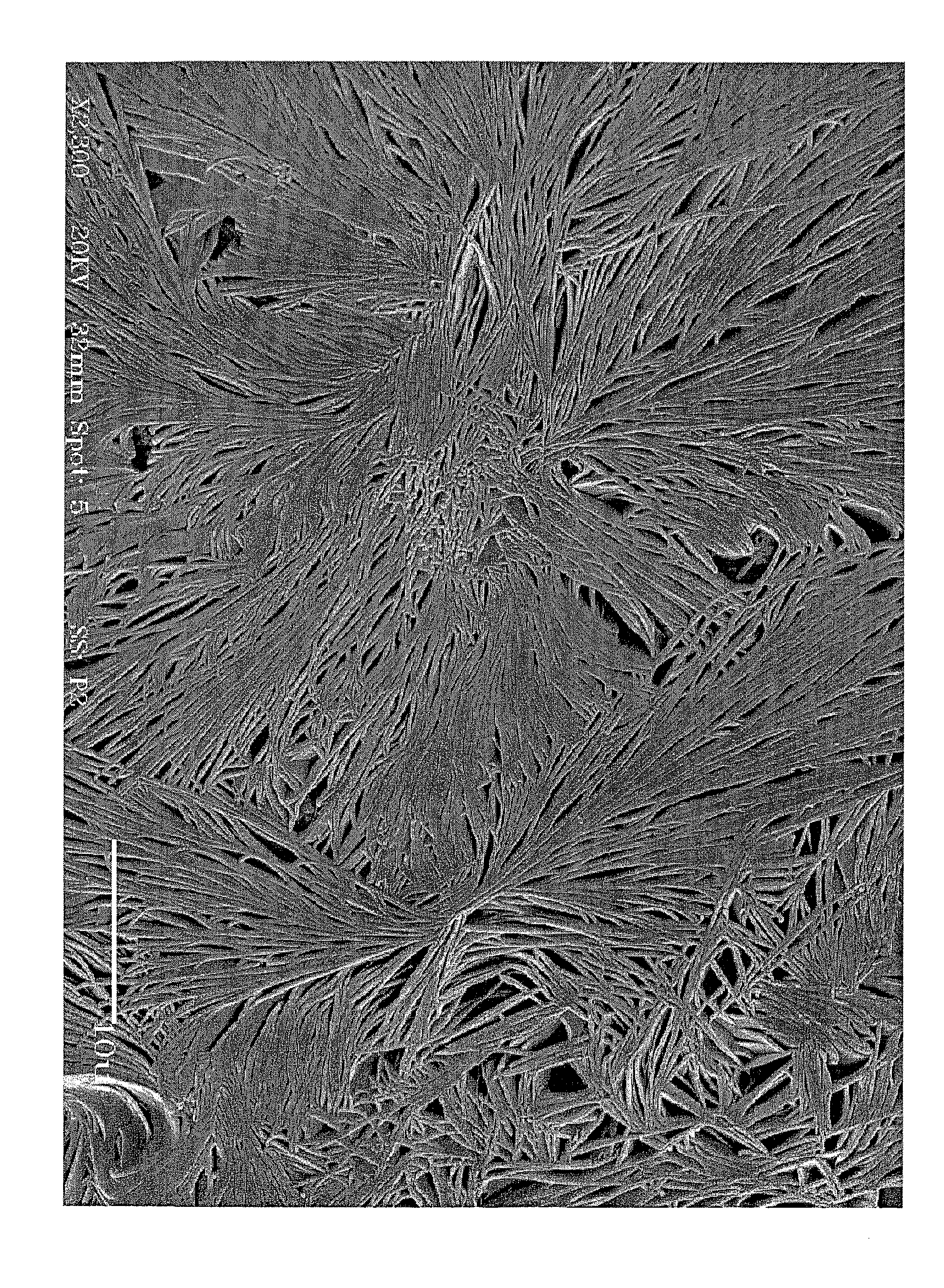
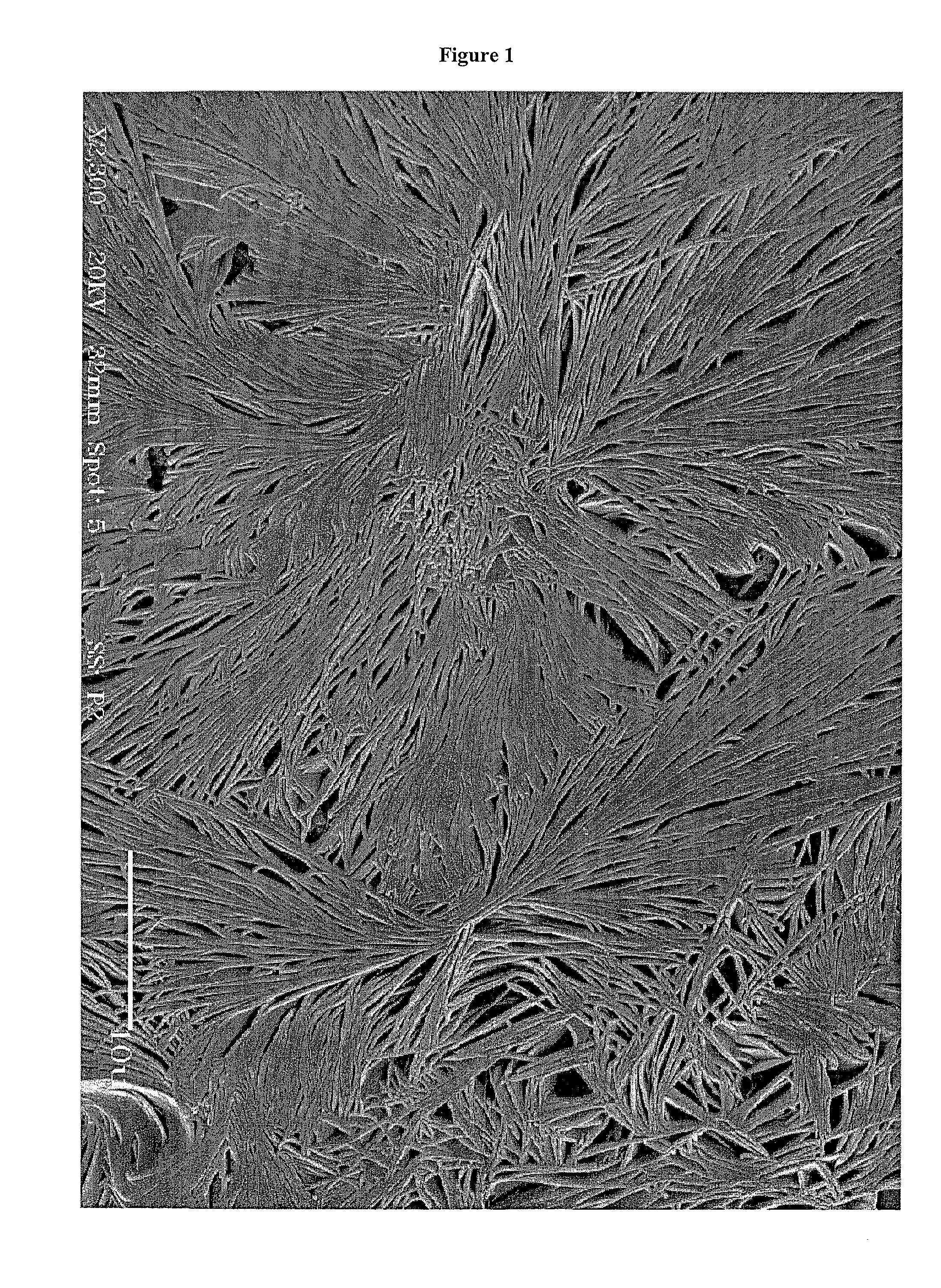
[0042]A first microemulsion comprised of 2 ml of 30% ammonium hydroxide plus 2.4 ml of water plus 66 ml of 0.50M AOT-isooctane and a second microemulsion comprised of 0.384 g of FeSO4.7H2O and 0.192 of NiSO4.6H2O dissolved in 8 ml water plus 66 ml of AOT-isooctane were prepared. Also prepared was a reactant salt solution comprised of hydrated iron sulfate and hydrated nickel sulfate in stoichiometric quantities according to the product, NiFe2O4 (i.e., [Fe+2] / [Ni+2]=2). Ammonium hydroxide is the precipitating agent in the first microemulsion. The two microemulsions were blended together and subjected to rapid mechanical stirring while under the influence of a magnetic field. The strength of the magnetic field was about 1000 Orested. Magnetic nanorods comprised of nickel ferrite were precipitated in a dendritic pattern within the water pools of reverse micelles.

[0043]The Figure hereof shows the architectural transformation of nanoparticles of nickel ferrite to nickel ferrite nanorods ...


PUM

PropertyMeasurementUnit
carbon numberaaaaaaaaaa
diameteraaaaaaaaaa
temperatureaaaaaaaaaa

Abstract

Magnetic nanostructures comprised of an assembly of magnetic nanorods held together by dipole forces in a dendritic pattern and their method of manufacture. The dendritic magnetic nanostructures are prepared at room temperature by applying a magnetic field to a reverse micelle system wherein at least one salt of a magnetic metal is being precipitated within the core of the reverse micelle.

Description

CROSS REFERENCE TO RELATED APPLICATIONS[0001]This application is a divisional of U.S. Ser. No. 11 / 361,212, which is a continuation-in-part of U.S. Ser. No. 11 / 051,273, filed Feb. 4, 2005, which issued as U.S. Pat. No. 7,504,130 on Mar. 17, 2009.FIELD OF THE INVENTION[0002]The present invention relates to magnetic nanostructures comprised of an assembly of magnetic nanorods held together by dipole forces in a dendritic pattern and their method of manufacture. The dendritic magnetic nanostructures are prepared at room temperature by applying a magnetic field to a reverse micelle system wherein at least one salt of a magnetic metal is being precipitated within the core of the reverse micelle.BACKGROUND OF THE INVENTION[0003]Quasi one-dimensional magnetic nanostructures, such as nanorods, nanowires, and nanotubes have attracted significant scientific and technological interest because they exhibit unique magnetic properties not displayed by their bulk or nanoparticle counterparts. Cryst...

Claims


Application Information

Patent Timeline
Patent Type & Authority Applications(United States)
IPC IPC(8): H01F1/04
CPCB82Y25/00Y10T428/12181C01G49/0009C01G49/0018C01G53/00C01P2004/16C01P2004/32C01P2004/62C01P2004/84C01P2006/42H01F1/0072H01F1/344C01G23/047C01P2004/01Y10S977/811Y10S977/838Y10S977/777Y10S977/754Y10T428/2991B82Y30/00
Inventor MISRA, DEVESH KUMAR
Owner UNIVERSITY OF LOUISIANA AT LAFAYETTE
Why Eureka
Try Eureka