Magnetic storage medium and magnetic recording device

a magnetic recording and magnetic storage medium technology, applied in the field of magnetic storage medium and magnetic recording device, can solve the problems of difficult to maintain a stable servo pattern, and achieve the effect of accurate detection of a position

Inactive Publication Date: 2010-02-11
KK TOSHIBA
View PDF5 Cites 3 Cited by
  • Summary
  • Abstract
  • Description
  • Claims
  • Application Information

AI Technical Summary

Benefits of technology

[0017]With the foregoing in view, it is an object of the present invention to provide a magnetic storage medium and magnetic recording device for accurately detecting a p

Problems solved by technology

However in the micro position detection portion, the second magnetic dots, which have a larger area than the first magnetic dots in the data area, have a low coercive force, and therefore even if an

Method used


Image

  • Magnetic storage medium and magnetic recording device
  • Magnetic storage medium and magnetic recording device
  • Magnetic storage medium and magnetic recording device

Examples


first embodiment

of a Magnetic Storage Medium

[0081]FIG. 4 is a diagram depicting a configuration of a magnetic storage medium according to a first embodiment of the present invention, and FIG. 5 is an enlarged view of the portion F enclosed by the broken line in FIG. 4. FIG. 4 and FIG. 5 show only the micro position detection portion 24 and the data portion 11.

[0082]As FIG. 4 and FIG. 5 show, in the data area 11, a first magnetic dot 41 is disposed evenly in the circumference direction and radius direction of the magnetic disk medium 1. The interval thereof is Tq in the circumference direction, and Tp in the radius direction. The dash and dotted line in FIG. 4 and FIG. 5 show a respective center line of a recording track T0, T1, . . . T4, which is a row of the first magnetic dots 41 in the circumference direction.

[0083]The first magnetic dot 41 is formed of ferro-magnetic poly-crystals, such as Co—Cr—Pt. Around the first magnetic dot 41, non-magnetic substance 44, such as silica, alumina and air, is...

second embodiment

of a Magnetic Storage Medium

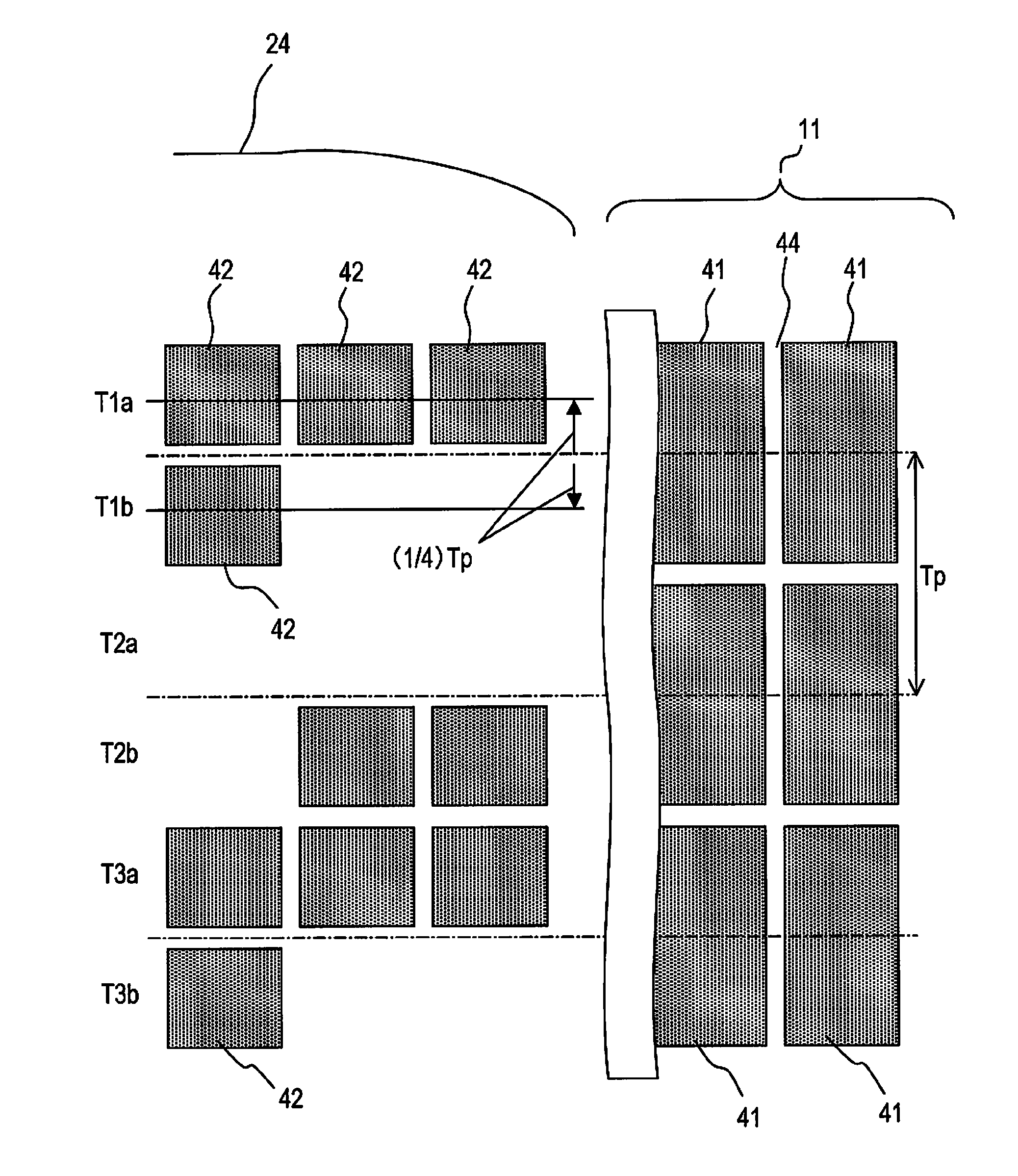
[0140]FIG. 18 is a diagram depicting the servo area and data area of the magnetic recording medium of the second embodiment of the present invention. FIG. 19 is an enlarged view of portion G in FIG. 18.

[0141]The second embodiment will now be described in comparison with FIG. 4, which depicts the first embodiment. In the case of the above-mentioned first embodiment, the second magnetic dot array having a cycle of 6Tq and a second magnetic dot array having a cycle of 8Tq are alternately disposed while reversing the phase, in the micro position detection portion 24 of the servo area.

[0142]Whereas in the case of the second embodiment in FIG. 18, a magnetic dot 42 which has a size roughly the same as the first magnetic dot 41 in the data area 11 is constructed by joining the second magnetic dots which adjoin in the radius direction.

[0143]In concrete terms, in the case of the second magnetic dot array in cycle 8Tq disposed on the track parallel line T1a in FIG....

third embodiment

of a Magnetic Storage Medium

[0149]FIG. 20 is a diagram depicting the servo area and data area of the magnetic storage medium according to the third embodiment of the present invention.

[0150]In the first and second embodiments, the micro position detection portion 24 of the servo area is comprised of second magnetic dot arrays in the cycle 8Tq and cycle 6Tq, which are disposed alternately on the track parallel lines T0a, T0b, T1a, T1b, . . . at a ½ pitch of the pitch Tp of recording tracks T0, T1, T2 . . . comprised of the first magnetic dots 41, in the data area.

[0151]However, the micro position detection portion 24 may be constructed by second magnetic dot arrays in different cycles. As FIG. 20 shows, the micro position detection portion 24 of the servo area is constructed using a second magnetic dot array in cycle 10Tq and second magnetic dot array in cycle 4Tq. In other words, five second magnetic dots continue at a position T1a, which is (½) Tp pitch away from the center axis of...


PUM


Abstract

A patterned media type magnetic storage medium has separated magnetic dots formed a data area having a first magnetic dots and a servo area. The micro position detection portion in the servo area is constructed with first and second dot arrays having a different number of second magnetic dots in the circumference direction and face with the center line that the first magnetic dots of the data area in the magnetic storage medium are disposed, as the axis. The area of the magnetic dot constituting the micro position detection portion of the servo area is small, so the coercive force of the servo area increases. The frequency is changed depending on the number of magnetic dots, and the phase is changed depending on the position of the magnetic dot array in the radius direction with the center line as an axis.

Description

CROSS-REFERENCE TO RELATED APPLICATION[0001]This application is based upon and claims the benefit of priority of the prior Japanese Patent Application No. 2008-201737, filed on Aug. 5, 2008, the entire contents of which are incorporated herein by reference.FIELD[0002]The present invention relates to a magnetic storage medium used for recording / reproducing information and a magnetic recording device which uses the magnetic storage medium, and more particularly to a magnetic storage medium having magnetic dots which is separated a magnetic recording material by a non-magnetic recording material, and a magnetic recording device which uses the magnetic storage medium.DESCRIPTION OF THE RELATED ART[0003]Recently a patterned media type magnetic storage medium is attracting attention as a technology to improve the recording capacity of magnetic recording devices. The patterned media type magnetic storage medium is a recording medium where uniform size micro-crystal grains having magnetism ...

Claims


Application Information

Patent Timeline
IPC IPC(8): G11B21/02G11B5/82
CPCB82Y10/00G11B5/59688G11B5/855G11B5/82G11B5/743
Inventor KAWABE, TAKAYUKI
Owner KK TOSHIBA
Why Eureka
Try Eureka