
Windshield washer fluid heater and system

a technology of fluid heater and windshield washer, which is applied in the field of windshield washer fluid heater and system, can solve the problems of reducing agility to scrape, driving dissatisfaction with slow and otherwise poor performance, and especially difficult access to windshields

Inactive Publication Date: 2010-02-18
SEEVA TECH INC
View PDF43 Cites 37 Cited by
  • Summary
  • Abstract
  • Description
  • Claims
  • Application Information

AI Technical Summary

Benefits of technology

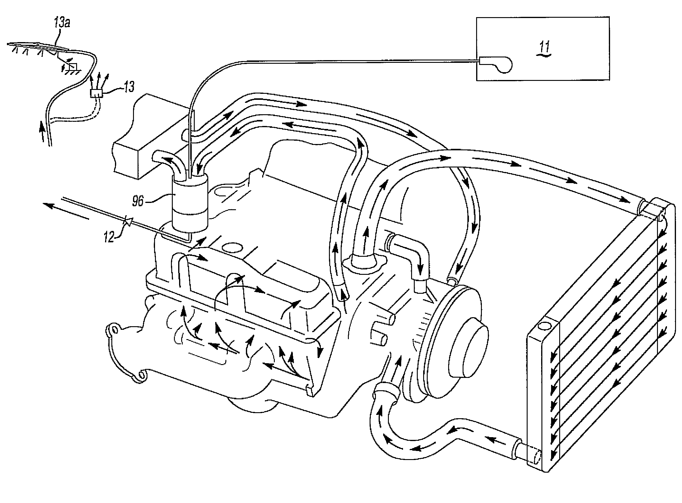
[0033]In operation, the engine coolant rapidly warms washer fluid flowing through the annular chamber which is then expelled onto the engine windshield.

Problems solved by technology

There continues to be much driver dissatisfaction with the slow and otherwise poor performance of these defrosters for providing quick and safe driving visibility.
Consequently, in commonplace operation drivers often have to scrape ice from the windshield and knock ice off wiper blades or waste fuel and time waiting for the engine to warm up so the defrosters can work.
Windshields are especially difficult to access effectively with ice scrapers, and the situation is exacerbated in the U.S.A. with the coming wave of 78 million elderly “baby boomers” having reduced agility to scrape ice from windshields.
Present day conventional type vehicles of lesser fuel efficiency and greater “waste heat” will largely become obsolete.
However anti-idling laws of many states and countries, in the interest of reducing air pollution and improving fuel economy, increasingly limit allowable idle time (now typically down to 5 minutes) and the remote start feature will tend to have corresponding idle time restrictions.
Electrically heated windshields can substantially reduce defrost time but have had limited use because of cost, complexity, poor reliability, and technical problems such as interference with electronic communications devices.
Visible heating wires and heating films can also be distracting and degrade windshield clarity and transparency.
Electrical overheating failure has resulted in at least one major product recall.
Still, even these systems exhibit poor performance, functionality and reliability in the opinion of many users.
Also, when driving in winter icing and blizzard conditions in which visibility becomes poor from iced up wipers and windshield, even with the aid of the warm air defroster on maximum output, available heated washer systems fail to quickly and effectively clear ice and often the driver still has to manually deice the wipers and windshield to achieve safe driving visibility.
These heated washer systems commonly do not respond instantly upon driver demand to spray heated washer fluid.
Confusing heated washer driver operated switch controls, along with already and increasingly complex modern instrument panel controls and displays, further add to the complexity and cost of these systems.
Heated washer systems using heat from engine coolant have long been available but also have had little success in the marketplace largely due to slow time to warm up upon engine cold start, low heat transfer rates, issues with washer heater freeze up damage and the heater purging its fluid from boiling of the high vapor pressure alcohol antifreeze laden washer fluid (about 158° F. boiling temperature) in the presence of 200+° F. engine coolant temperatures.
Purging not only can waste washer fluid but, more importantly, causes significant delay in spray time from the resulting empty washer fluid heater having to become refilled, and the cold fluid then entering the heater does not have sufficient time to fully heat up as it quickly passes through the heater to get sprayed to the windshield.
Heated washer fluid spray concentrating, and therefore high windshield thermal shocking, conventional nozzles, even of the wider spraying fluidic and spray fanning types, fail to provide the very high degree of broad and uniform heated fluid distribution needed to bring out the great deicing and bug clearing performance capability of an otherwise well engineered heated washer system.
Another deficiency of available heated washer systems is that they cause the heated fluid to lose a large part of its heat energy through rapid wind chill evaporative cooling of the contained high vapor pressure alcohol antifreeze as the fluid sprays from the nozzles a foot or two through the cold air before reaching the mid and upper reaches of the windshield.
The resulting large amount of midair condensing visible steam on actual tests by this inventor is clear evidence of this energy loss.
This sudden cloud of steam can also cause momentary reduction of driver visibility, e.g. while making a left turn in the presence of oncoming traffic on a sunny day.
Often washer systems will be filled with water based fluid having insufficient antifreeze which subsequently freezes solid and causes washer heater permanent damage from ice expansion pressure.
Washer heater design features to provide freeze protection typically add cost, and the increased complexity can run counter to increasing reliability.
Another shortcoming of available washer fluid heaters is that their effectiveness is inherently limited because, in between the short electronically programmed heated fluid squirts, the remaining heat of the fluid on the windshield and the now slightly warmed glass is quickly dissipated by evaporation and wind chill during the frequent and long fluid reheating delays between these short squirts.
The result is delayed defrosting and even partial windshield refreezing while awaiting subsequent programmed heated short squirts which have to reheat the remaining ice to its melting point.
This results in extended defrost times best measured in minutes.
Another deficiency of available washer fluid heaters is that they are prone to building up calcium scale and other mineral deposits from the long term heating of washer fluid continuously stored within the heating chamber.
These deposits can choke fluid passage, cause loss of heat transfer efficiency and break loose and clog washer nozzles.

Method used


Image

  • Windshield washer fluid heater and system
  • Windshield washer fluid heater and system
  • Windshield washer fluid heater and system

Examples


Embodiment Construction

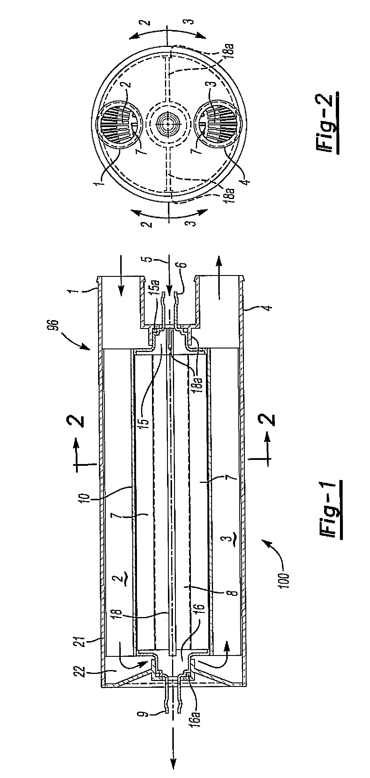
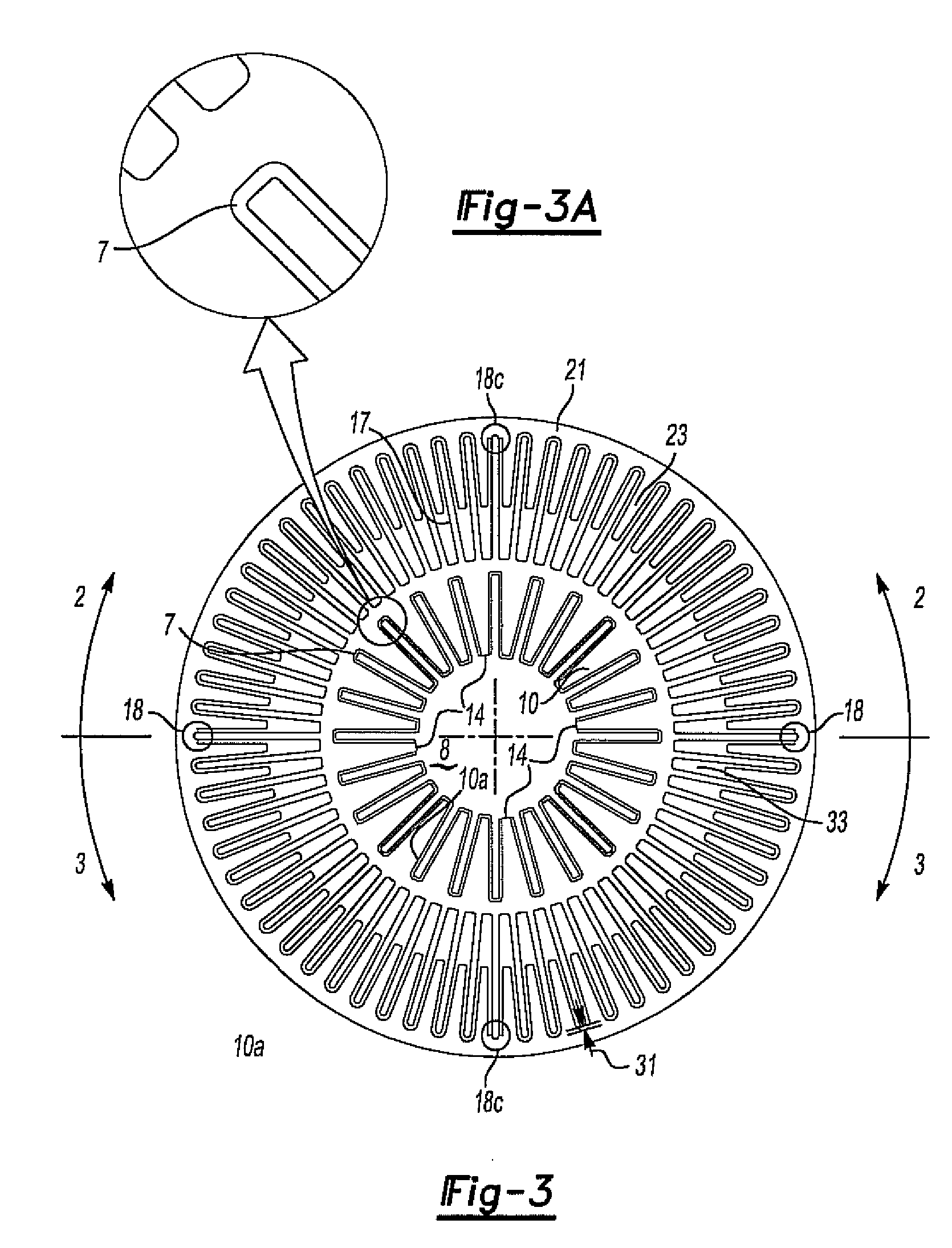
[0069]FIGS. 1-6 show construction of a washer fluid heater 96 using engine coolant (or other suitable fluid) as a heat source. This construction also shows a minimal component parts count of 8 pieces.

[0070]Warm engine coolant flows from the off center inlet hose barb 1 through an outer housing chamber 2 to the opposite end 22 of the heater then crosses over to the opposite side outer finned annulus half circular heat transfer chamber 3 and returns to the outlet hose off center barb 4. Outer finned half annuli 2 and 3 are sealingly separated at linear contact points 18 for the full length of the finned annuli and at coolant barb end dam 18a. Cold washer fluid 5 enters at its on-center inlet barb 6 on one end of the heater and flows very evenly distributed through the inner finned heat transfer chamber 7 with matching male finned and very closely and evenly spaced—approximately 0.010 inch constant clearance—center core 8, to opposite end on-center heated fluid outlet barb 9. The inter...


PUM


Abstract

A windshield washer fluid heater having a housing which defines a housing chamber. A subhousing is disposed in the housing chamber. This subhousing is constructed of a thermally conductive material and divides the housing chamber into an outer housing chamber between the housing and the subhousing, and an inner housing chamber inside the subchamber. The outer housing chamber and inner housing chambers are fluidly isolated from each other. A core is disposed in the inner housing chamber thus forming an annular fluid chamber between the core and the subhousing. A washer fluid inlet on the housing is open to one end of the annular chamber while a washer fluid outlet at the other end is open to the other end of the annular chamber An engine coolant inlet is open to the outer chamber while an engine coolant outlet is also open to the outer chamber at a position spaced from the inlet so that fluid flow into the coolant inlet flows through the outer housing chamber and to the coolant outlet. Alternatively, an electric heater is used to heat the housing chamber containing the annular fluid chamber.

Description

CROSS-REFERENCE TO RELATED APPLICATION[0001]This application claims priority of U.S. Provisional Patent Application Ser. No. 61 / 089,577 filed Aug. 18, 2008, which is incorporated herein by reference.BACKGROUND OF THE INVENTION[0002]1. Field of the Invention[0003]The present invention relates to vehicle windshield defrosters and wipers using heated washer fluid.[0004]2. Description of Related Art[0005]Defrosting and deicing of motor vehicle windshields and wipers have been served by conventional warm air defrosters for many decades. There continues to be much driver dissatisfaction with the slow and otherwise poor performance of these defrosters for providing quick and safe driving visibility. Government mandated vehicle safety standards (e.g. FMVSS103 based on 1960s warm air automotive defroster minimal technology) set minimum defrosting performance requirements, yet still allow 30 minutes from cold engine start to clear a preset standard amount of frost at 0° F. Even modern (27.5 m...

Claims


Application Information

Patent Timeline
Patent Type & Authority Applications(United States)
IPC IPC(8): B60S1/48
CPCB60H1/00271B60H1/242B60S1/023F01P3/12B60S1/524B60S1/54B60S1/487B60S2001/3898
Inventor LANSINGER, JERE R.
Owner SEEVA TECH INC
Learn More