
Source and output device-independent pixel compositor device adapted to incorporate the digital visual interface (DVI)

a pixel comparator and source device technology, applied in the field of source and output device-independent pixel comparator device adapted to incorporate the digital visual interface, can solve the problems of limited performance of conventional, limited nature of conventional specialized projectors, and no current system providing the flexibility of new pixel comparator devices

Inactive Publication Date: 2010-02-18
UNIV OF KENTUCKY RES FOUND UKRF A NON PROFIT ORG EXISTING UNDER THE STATE COMMONWEALTH OF KENTUCKY WITH OFFICES AT
View PDF7 Cites 14 Cited by
  • Summary
  • Abstract
  • Description
  • Claims
  • Application Information

AI Technical Summary

Benefits of technology

[0027]Briefly described, in one characterization, the invention is directed to a unique pixel compositor device for routing an incoming stream of pixel data having been rendered elsewhere and bound for being projected. The device includes a plurality of digital signal inputs each adapted for receiving a plurality of pixel information from the incoming stream of pixel data. The digital signal inputs are in communication with at least one buffer providing temporary storage for the pixel information once received by the device. A processing unit is included for image warping the pixel information by performing, on each of a respective of the pixel information: (i) a mapping relating to location of the respective pixel information, and (ii) a scaling function. The geometric mapping can be performed by applying any of a number of suitable interpolation techniques (nearest-neighbor interpolation, bilinear interpolation, trilinear interpolation, and so on) and the scaling function can be any of a number of known photometric correction functions (alpha-blending, typically carried out by applying a per-pixel scale factor to each respective pixel information, color uniformity correction, image brightness or contrast adjustment, and so on). Once an image warping has been performed on the respective pixel information, it is routed out of the device through one of several digital signal outputs. A system for routing pixel data is also disclosed having two or more of the pixel compositor devices in communication with an image rendering cluster of computerized units (the source of the incoming stream of pixel data) and a plurality of projectors; as is a method for routing an incoming stream of pixel data having been rendered elsewhere and bound for being projected.

Problems solved by technology

(2001) and HDVG (www.orad.co.il) systems are both limited to performing conventional compositing tasks in which each video stream is restricted to a rectilinear region in the final output, i.e., the routing is limited to block transfer of pixels.
None of the current systems provide the flexibility of the new pixel comparator device disclosed herein.
Further, the limited nature of conventional specialized projectors make them unavailable for direct tie-into a multi-projector display that has overlaps, since one projector would need part of the images from its neighborhood in the overlap region.
That is, the classic mapping and warping function capabilities of conventional digital projection hardware is very limited: Currently-available systems are created as dedicated complex systems that necessarily view motional images (digital video or film) bound for digital projection.
Thus, the conventional systems are only capable of simple overall scaling and translation of the image information on a large scale using global pixel warping based on a set of pre-defined, known parametric functions.
Prior systems are limited to simple linear mapping.

Method used


Image

  • Source and output device-independent pixel compositor device adapted to incorporate the digital visual interface (DVI)
  • Source and output device-independent pixel compositor device adapted to incorporate the digital visual interface (DVI)
  • Source and output device-independent pixel compositor device adapted to incorporate the digital visual interface (DVI)

Examples


example 01

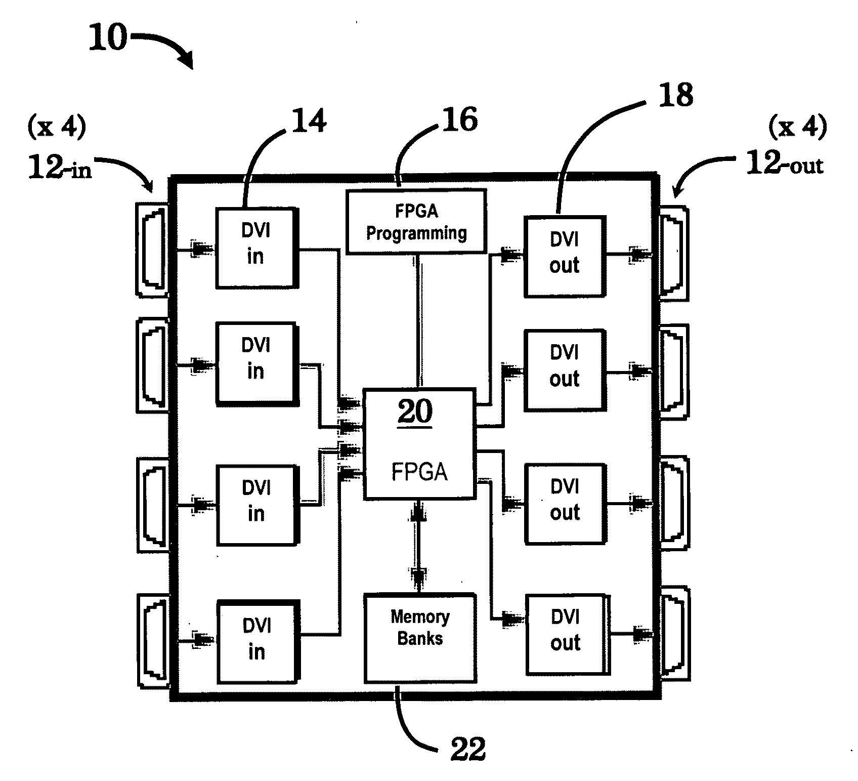
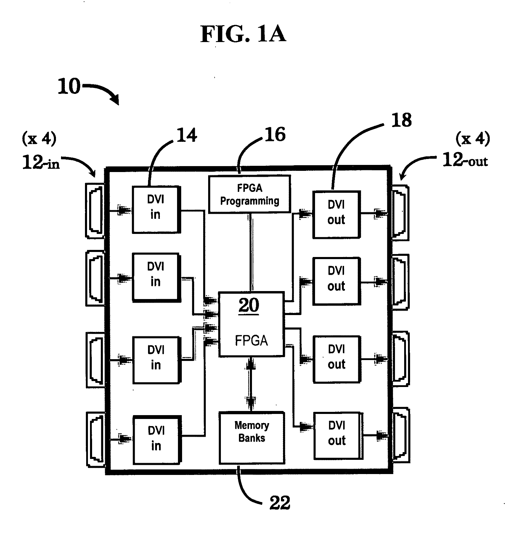
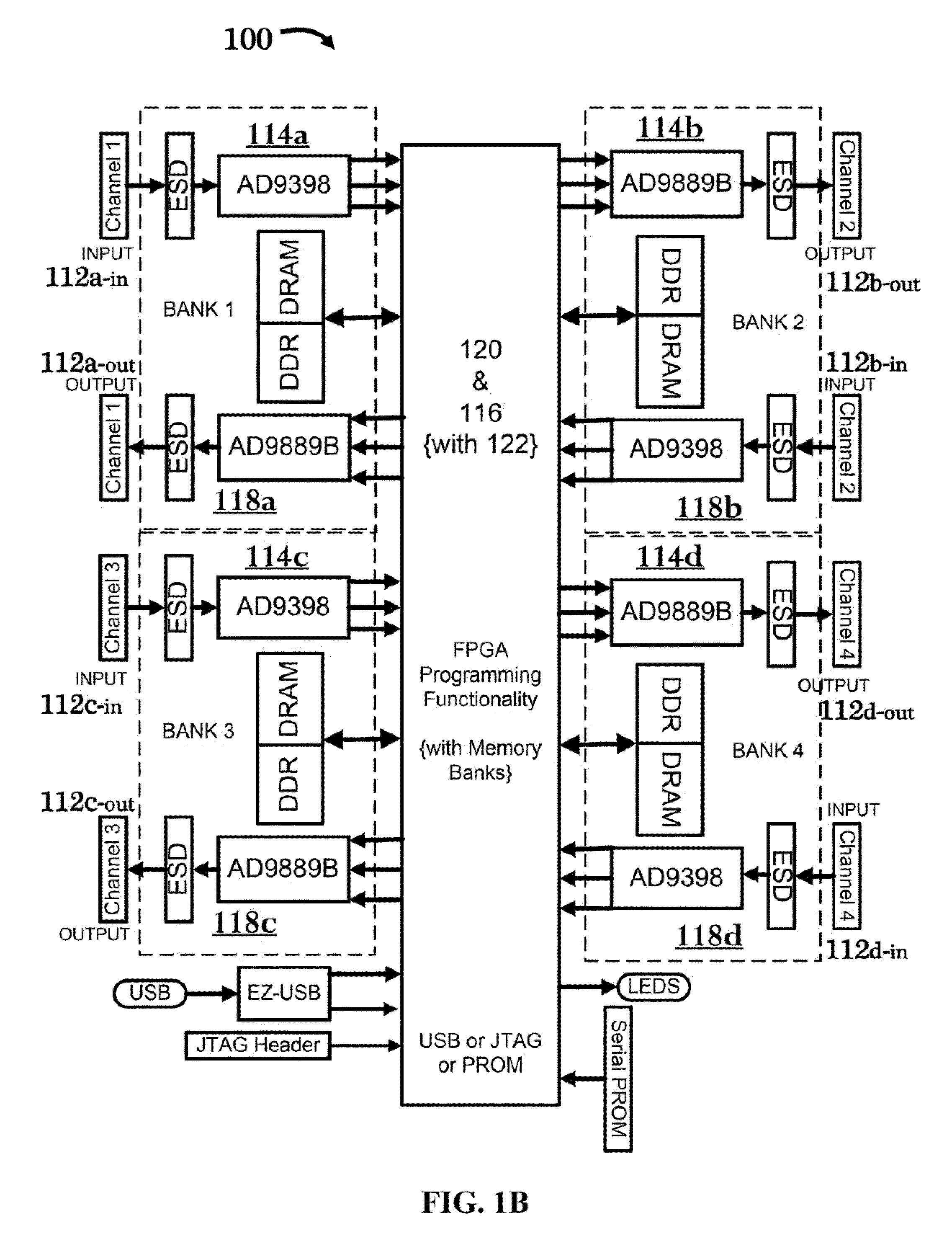
[0054]FIG. 4 is a diagram representing data flow through a compositor device such as 10, 100 in the form of a preferred alternative embodiment. FIG. 5 is an arbiter state machine state diagram representing a preferred alternative approach to reading from input FIFO's and writing to buffers, as represented and labeled in FIG. 4. Core, as well as further distinguishing features of FIGS. 4 and 5 (and others), have been woven together in this EXAMPLE 01, by way of example only, providing details of device and system components—and associated functionalities—to further illustrate the unique nature of pixel compositor device and method 10, 10a-h, 100, 400, 600.

[0055]A Xilinx VIRTEX-4 FPGA core, 256 MB of DDR RAM arranged on four independent buses, and 4 HDMI inputs and 4 HDMI outputs. The HDMI interface is backward compatible with the DVI interface. The FPGA core can be run at 200 MHz. The input image information is preferably buffered (INPUT BUFFER A and B, FIG. 4). To achieve a target o...


PUM


Abstract

A pixel compositor device for routing an incoming stream of pixel data having been rendered elsewhere and bound for being projected. The device includes a plurality of digital signal inputs each adapted for receiving a plurality of pixel information from the incoming stream of pixel data. The digital signal inputs are in communication with at least one buffer for the pixel information once received by the device. A processing unit is included for image warping the pixel information by performing, on each of a respective of the pixel information: (i) a mapping relating to location of the respective pixel information, and (ii) a scaling function. The geometric mapping can be performed by applying an interpolation technique; and the scaling function can be any of a number of photometric correction functions (alpha-blending, color uniformity correction, image brightness or contrast adjustment, etc.). Once an image warping has been performed on the respective pixel information, it is routed out of the device through one of several digital signal outputs. A system for routing pixel data is disclosed having two or more of the pixel compositor devices in communication with an image rendering cluster of units (as the source of the incoming stream of pixel data) and a plurality of projectors; as is a method for routing an incoming stream of pixel data having been rendered elsewhere and bound for being projected.

Description

[0001]This application claims priority to pending U.S. provisional patent app. No. 61 / 123,529 filed 9 Apr. 2008 on behalf of the assignee hereof for the applicants hereof. To the extent consistent with the subject matter set forth herein, provisional app. No. 61 / 123,529 and its EXHIBITS are hereby fully incorporated, herein, by reference for background and full technical support.[0002]The invention disclosed in this provisional application was made with United States government support awarded by the following agencies: U.S. Department of Homeland Security, 2005-2006 contract; and the National Science Foundation (NSF) award number IIS-0448185. Accordingly, the U.S. Government has rights in this invention.BACKGROUND OF THE INVENTIONField of the Invention[0003]In general, the present invention relates to computer-implemented systems and techniques for interconnecting one or more video or motion-picture source devices (e.g., a personal computer, “PC”, or a DVD player) with a multitude ...

Claims


Application Information

Patent Timeline
Patent Type & Authority Applications(United States)
IPC IPC(8): H04N9/31G09G5/00G09G5/36G06F3/038H04N11/06
CPCG06F3/1423G09G3/001G09G3/003G09G5/003G09G5/36H04N9/3147G09G2320/0626G09G2320/066G09G2340/10G09G2352/00G09G5/395
Inventor YANG, RUIGANGLASTRA, ANSELMO
Owner UNIV OF KENTUCKY RES FOUND UKRF A NON PROFIT ORG EXISTING UNDER THE STATE COMMONWEALTH OF KENTUCKY WITH OFFICES AT
Learn More