
Piston-driving rod arrangement for reciprocating compressor

a technology of rotating rods and compressors, which is applied in the direction of machines/engines, mechanical equipment, and positive displacement liquid engines, etc., can solve the problems of accelerated wear of components, increase of energy consumption, and decrease of compressor efficiency, so as to promote higher load and wear resistance, improve hydrodynamic pressure, and improve the effect of pressur

Inactive Publication Date: 2010-02-18
WHIRPOOL SA
View PDF4 Cites 0 Cited by
  • Summary
  • Abstract
  • Description
  • Claims
  • Application Information

AI Technical Summary

Benefits of technology

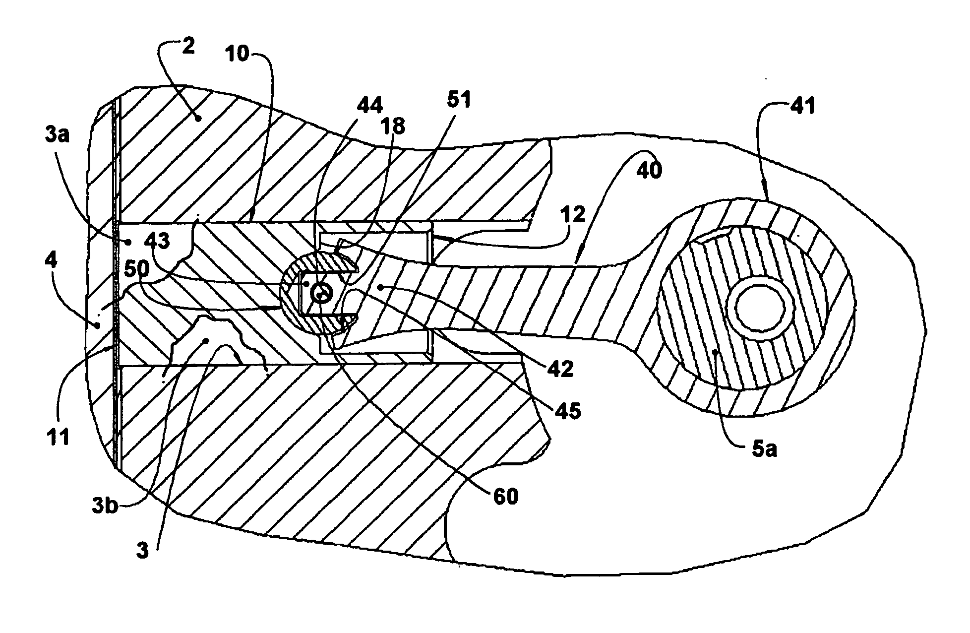
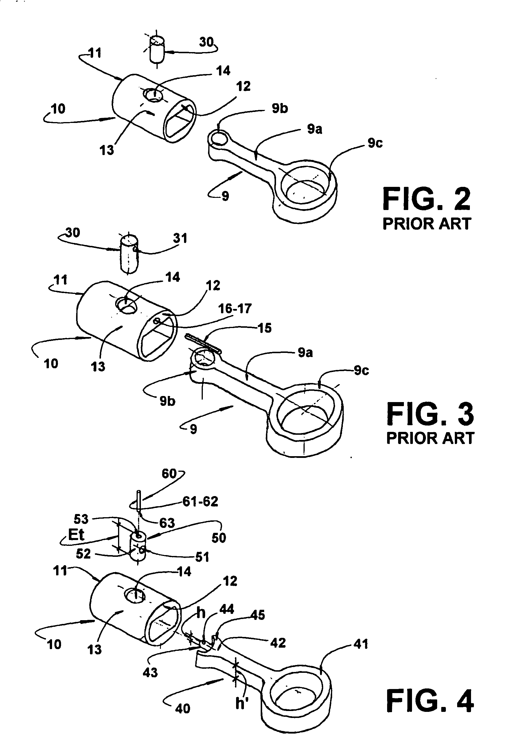
[0014]Thus, it is an object of the present invention to provide a mounting arrangement for a driving rod and piston of a reciprocating compressor, which allows increasing the supporting area of the joint pin in relation to the piston and which improves the load resistance of said piston, mainly during the compression stroke, without requiring a reduction in the dimensions of the joint pin, particularly of its diameter.
[0015]A further object of the present invention is to provide a mounting arrangement as cited above, which enables a simple and fast mounting of the driving rod-piston assembly, by utilizing components which do not require high dimensional precision, do not cause accelerate wear of the involved parts and keep the reliability of the product, even in limit lubrication conditions.
[0018]The present invention allows the provision of a bearing in the piston which, mainly for pistons of reduced dimensions, for example, with diameter smaller than 19 mm, has a larger supporting area in the region of higher pressure, during compression of the refrigerant fluid at the upper dead point of the piston. Said larger supporting area improves the hydrodynamic pressure, which promotes higher load and wear resistance of this bearing of the compressor.

Problems solved by technology

As it is known, the transverse reaction forces of the cylinder block against the piston can provoke excessive friction between the piston and the cylinder block, leading to an increase of energy consumption, with a consequent decrease in the efficiency of the compressor, as well as an accelerated wear of the components subject to greater friction levels, reducing the useful life of the compressor.
The known constructions of a two-piece connecting rod present inconveniences, such as: requiring a high number of components; having a difficult assembling; permitting the occurrence of large mass movement; generating residues, as in the case of welding or use of adhesive; and requiring precise machining, which involve high manufacturing costs.
When adhesive is used, there is also the inconvenience of requiring, sometimes, a long drying period.
Furthermore, the fixation through adhesives affects the reliability of the product, since the adhesive presents a variable resistance with time, due to material aging.
This solution presents, as disadvantage, the great difficulty to join the sphere to the end of the connecting rod in a reliable and adequate way, besides presenting a higher potential for localized wear during the operation of the compressor.
Moreover, this solution presents a load capacity, upon application of forces, smaller than that of the other known solutions for mounting the connecting rod to the piston.
This construction presents the deficiency of requiring a piston with a large length and thicker wall, increasing the area of contact with the inner walls of the cylinder, reducing the performance of the compressor.
In the constructions which require a reduction of the piston diameter, the conventional constructions for mounting the connecting rod to the piston are not applicable, since there is a reduction in the inner space of the piston to lodge the smaller eye of the connecting rod.
The accumulation of the not equally distributed load in the joint pin increases the wear thereon, reducing its useful life.

Method used


Image

  • Piston-driving rod arrangement for reciprocating compressor
  • Piston-driving rod arrangement for reciprocating compressor
  • Piston-driving rod arrangement for reciprocating compressor

Examples


Embodiment Construction

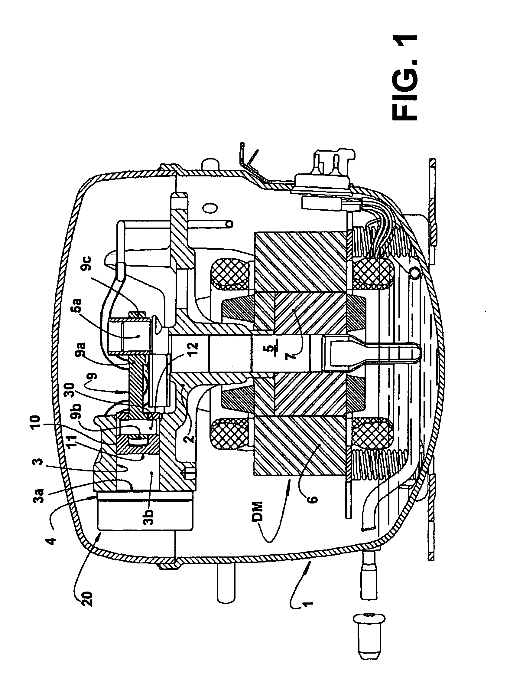
[0028]The present invention will be described for a reciprocating compressor driven by a linear motor or by a rotary motor, of the type utilized, for example, in small refrigeration systems of refrigeration appliances, and which comprises, mounted inside a hermetic casing 1, a motor-compressor assembly having a cylinder block 2, in which is defined a cylinder 3 lodging, at one end, a piston 10 reciprocating inside said cylinder 3, in suction and compression strokes of a compression cycle of refrigerant fluid. The cylinder 3 also presents an opposite end 3a closed by a cylinder cover or head 20 which defines, therewithin, a discharge chamber (not illustrated), which maintains a selective fluid communication with a compression chamber 3b defined in the interior of the cylinder 3, between the top portion 11 of the piston 10 and a valve plate 4 provided between the opposite end of the cylinder 3 and the head 20.

[0029]In the compressor of the type illustrated in FIG. 1, the piston 10 is ...


PUM


Abstract

The arrangement is applied to a reciprocating compressor comprising a reciprocating piston and a driving rod having one end coupled to a driving means and an opposite end cooperating with a joint pin mounted to the piston, and carrying one coupling longitudinal extension fitted in the joint pin and there retained so that the driving rod displaces the piston in its suction stroke. The joint pin is coupled to the piston during the compression stroke along a longitudinal extension of the side surface of the joint pin larger than the difference between the total longitudinal extension of the latter and the height of the opposite end of the driving rod.

Description

FIELD OF THE INVENTION[0001]The present invention refers to a mounting arrangement for a driving rod and a piston that reciprocates in the interior of a compression chamber of a reciprocating compressor provided with a conventional or linear electric motor and of the type utilized in refrigeration systems, particularly of small size, such as refrigerators, freezers, drinking fountains, etc.BACKGROUND OF THE INVENTION[0002]Hermetic compressors of the type utilized in refrigeration systems, which are driven by a rotary or linear electric motor, generally comprise, in the interior of a casing, a motor-compressor assembly having a cylinder block in which is defined a cylinder having one end closed by a head and which defines, therewithin, a discharge chamber in selective fluid communication with a compression chamber defined in the interior of the cylinder and closed by a valve plate provided between the closed end of the cylinder and the head, said fluid communication being defined thr...

Claims


Application Information

Patent Timeline
Patent Type & Authority Applications(United States)
IPC IPC(8): F04B39/00F16J1/12
CPCF04B39/14F04B39/0022F04B39/00
Inventor PEREIRA, MILTON WETZELMOREIRA, EMERSONMACIEL, RICHARDO ALEXANDREFAGOTTI, FABIANWEBER, GUSTAVO CARDOSO
Owner WHIRPOOL SA
Learn More