
Fuel cell system

a fuel cell and system technology, applied in the direction of functional valve types, operating means/releasing devices of valves, electrical generators, etc., can solve the problems of response delay and delay in opening/closing valves with respect, and achieve the effect of improving the response of the gas element component, reducing the time delay of injector control based on the pressure detected by the pressure sensor, and improving the response of the injector

Active Publication Date: 2010-02-18
TOYOTA JIDOSHA KK
View PDF5 Cites 12 Cited by
  • Summary
  • Abstract
  • Description
  • Claims
  • Application Information

AI Technical Summary

Benefits of technology

[0004]The present invention has been developed in view of such a situation, and an object thereof is to provide a fuel cell system capable of improving the response of a gas element component responding to the physical quantity of a reactant gas.
[0006]According to such a constitution, the gas element component is integrally provided in the injector to come close to the injector, and hence the response delay of the gas element component with respect to pressure fluctuations caused by the intermediate can be suppressed.
[0011]According to such a constitution, even when droplets attach to the open valve, the droplets are discharged from the downside, and can be prevented from attaching to the valve body.
[0015]According to such a constitution, even in a case where there occurs such an error that the injector does not return from a fully opened state to a fully closed state (so-called adhering to the opened state), more reactant gas can be discharged from the open valve to the outside of the reactant gas pipe through the branch passage portion having a large passage sectional area, and eventually a pressure applied to the fuel cell can be decreased.
[0021]According to such a constitution, since the pressure sensor is arranged close to the injector, the time delay of injector control based on the pressure detected by the pressure sensor can be decreased, and the response of the injector to the opening / closing control can be improved.
[0022]According to the present invention, there can be provided a fuel cell system capable of improving the response of the gas element component responding to the physical quantity of the reactant gas regulated by the injector on the upstream side.

Problems solved by technology

However, in a fuel cell system disclosed in Patent Document 1 described above, a flow rate regulation valve is arranged away from an open valve, and delay might occur in opening the open valve with respect to the fluctuations of a gas pressure regulated by the flow rate regulation valve on the upstream side.
Such response delay is a problem which might occur in not only the open valve but also various components, as long as the components are gas element components responding to the physical quantity of a reactant gas.

Method used


Image

  • Fuel cell system
  • Fuel cell system
  • Fuel cell system

Examples


first embodiment

[0033]Hereinafter, a fuel cell system 1 according to the present invention will be described with reference to FIGS. 1 to 8.

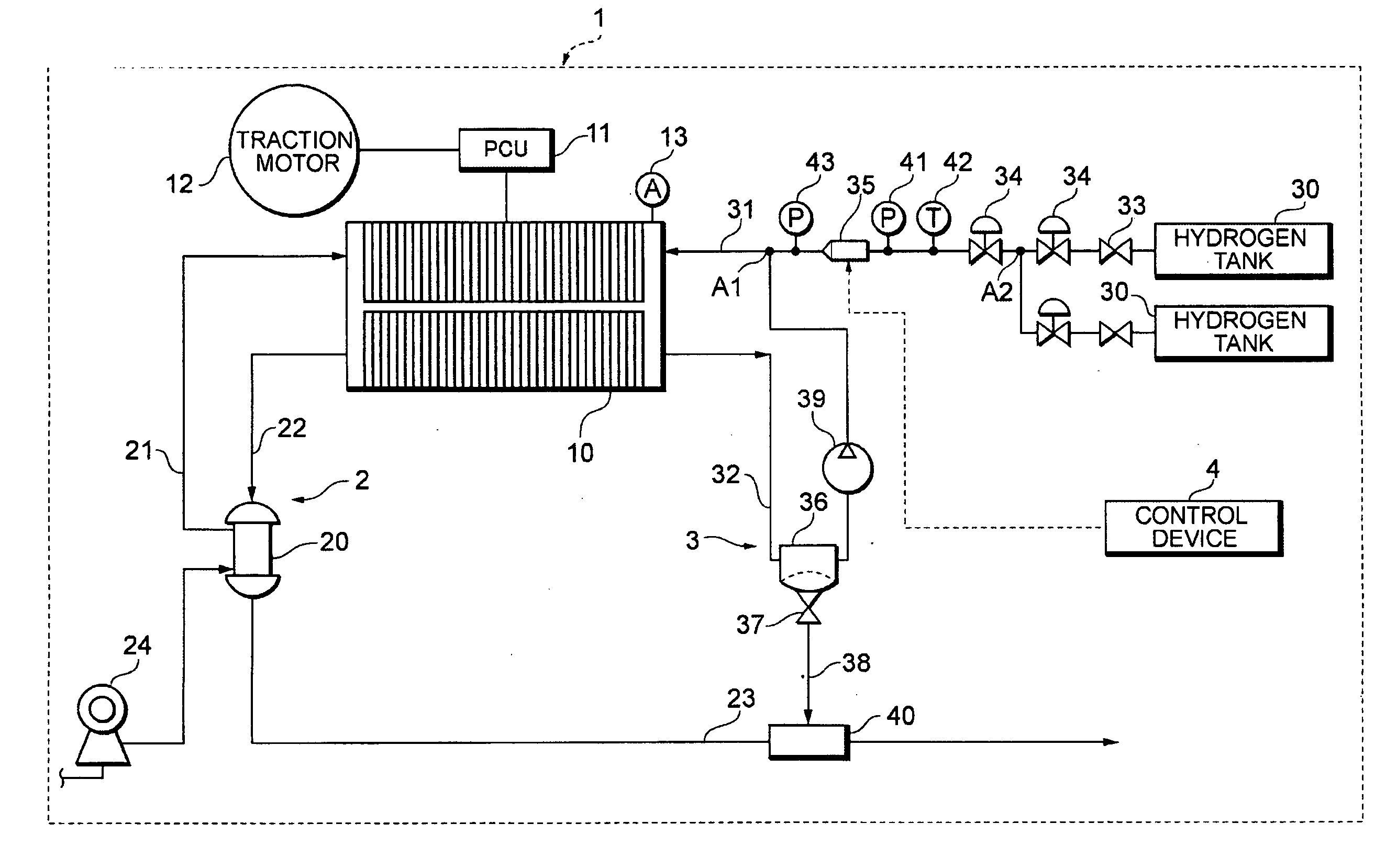
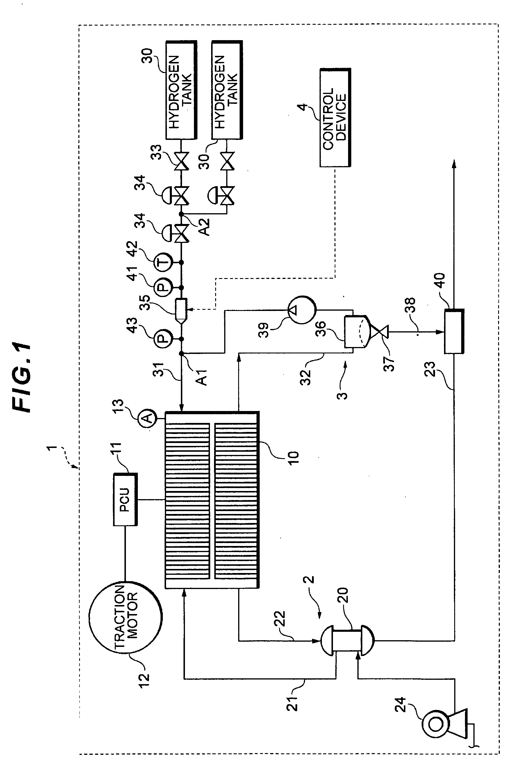
[0034]FIG. 1 is a system constitution diagram of the fuel cell system 1. This fuel cell system 1 can be applied to a car-mounted power generation system for a fuel cell car, a power generation system for any mobile body such as a ship, an airplane, a train or a walking robot, a further stational power generation system for use as a power generation facility for a construction (a housing, a building or the like) or the like, and the system is specifically used for the car.

[0035]As shown FIG. 1, the fuel cell system 1 according to the first embodiment includes a fuel cell 10 which receives a supplied reactant gas (an oxidizing gas and a fuel gas) to generate a power, and also includes an oxidizing gas piping system 2 which supplies air as the oxidizing gas to the fuel cell 10, a hydrogen gas piping system 3 which supplies a hydrogen gas as the fuel gas, a control...

second embodiment

[0099]Moreover, in the second embodiment, the open valve 131 is supported by a support block 84 which supports a cylindrical portion 45 on the upstream side of the injector 35 and a support block 87 which supports a cylindrical portion 46 on the downstream side, and the open valve connects these support blocks 84, 87 to each other.

[0100]That is, the upper support block 84 of the second embodiment is formed with a width larger than that of the first embodiment, along an end plate 72, additionally a fitting hole 133 is formed in parallel with a hole portion 85 for supporting the cylindrical portion 45, and the fitting hole 133 is connected to the hole portion 85 via a communication hole 134 crossing the fitting hole and the hole portion at right angles.

[0101]Moreover, the lower support block 87 is also formed with a width larger than that of the first embodiment, along the end plate 72, additionally a fitting hole 136 is formed in parallel with a hole portion 88 for supporting the cyl...

third embodiment

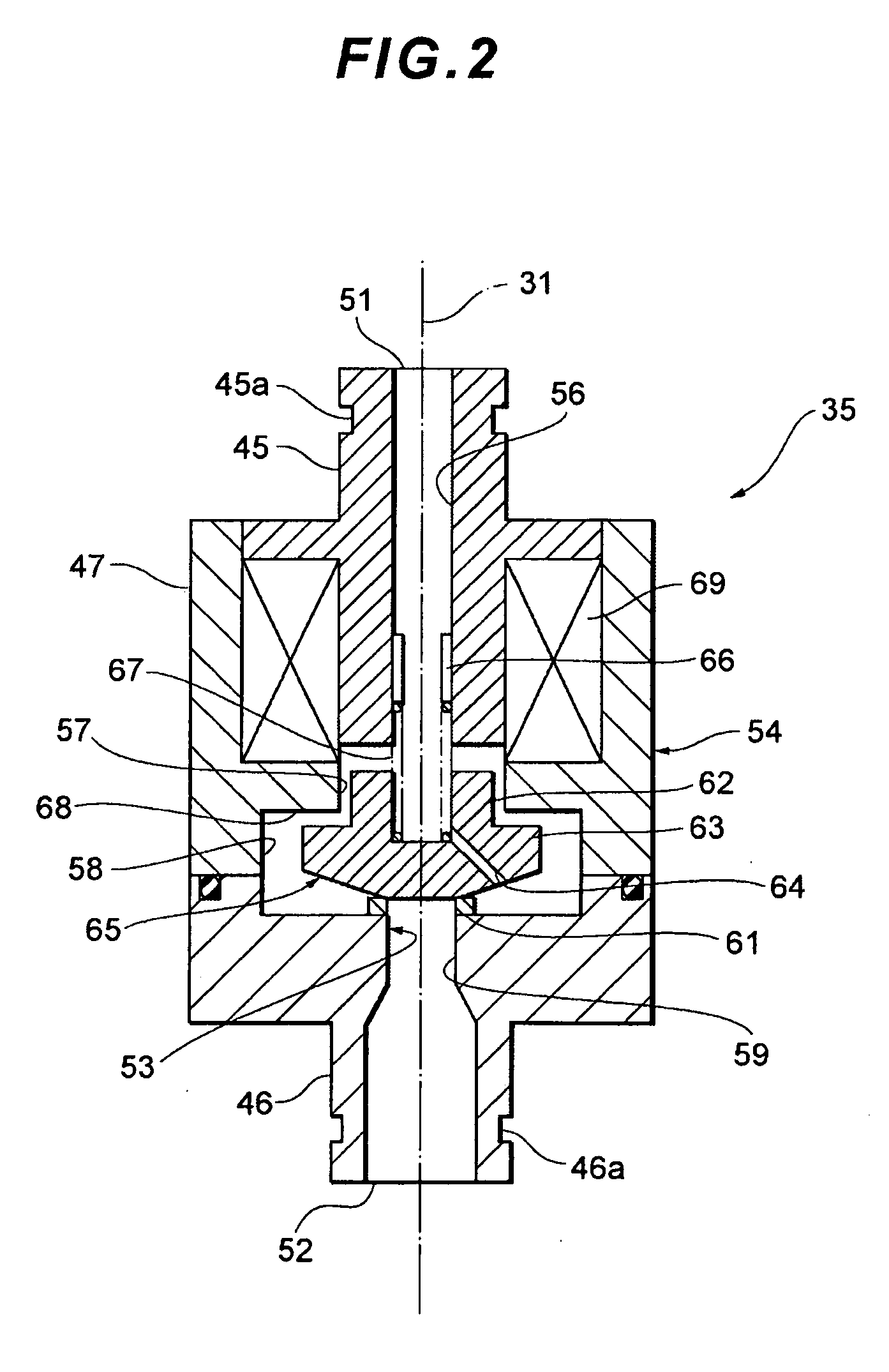
[0116]According to the fuel cell system 1 of the third embodiment described above, since the pressure sensors 41, 43 as the gas element components responding to the physical quantity of the reactant gas circulating through the hydrogen supply passage 31 are integrally provided in the injector 35 to come close to the injector, the response delay of the pressure sensors 41, 43 with respect to pressure fluctuations caused by the injector 35, that is, the time delay of the pressure detection by the primary pressure sensor 41 and the secondary pressure sensor 43 can be suppressed.

[0117]In consequence, as described above, the control delay of the injector 35 controlled based on the pressure value detected by the primary pressure sensor 41, the pressure value detected by the secondary pressure sensor 43 and the like can be suppressed.


PUM


Abstract

A fuel cell system having a fuel cell, a reactant gas pipe for supplying a reactant gas to the fuel cell, and an injector for driving a valve body at a predetermined drive cycle by an electromagnetic driving force to separate the valve body from a valve seat, regulating conditions of the gas on the upstream side in the reactant gas pipe and supplying the gas to the downstream side. A gas element component responding to the physical quantity of the reactant gas circulating through the reactant gas pipe is integrally provided in the injector so as to come close to the injector.

Description

TECHNICAL FIELD[0001]The present invention relates to a fuel cell system including an injector in a reactant gas pipe connected to a fuel cell.BACKGROUND ART[0002]At present, a fuel cell system including a fuel cell for receiving a supplied reactant gas (a fuel gas and an oxidizing gas) to generate a power has been suggested and put to practical use. In such a fuel cell system, a reactant gas pipe for allowing the fuel gas supplied from a fuel supply source such as a hydrogen tank to flow to the fuel cell is provided with a flow rate regulation valve which regulates gas conditions, and an open valve is provided on the downstream side of this flow rate regulation valve (e.g., see Japanese Patent Application Laid-Open No. 2002-134239).DISCLOSURE OF THE INVENTION[0003]However, in a fuel cell system disclosed in Patent Document 1 described above, a flow rate regulation valve is arranged away from an open valve, and delay might occur in opening the open valve with respect to the fluctuat...

Claims


Application Information

Patent Timeline
IPC IPC(8): H01M8/04
CPCF16K31/0651Y02E60/50H01M8/04201H01M8/04089H01M8/04F16K17/02F16K31/02
Inventor KATANO, KOJIYAMAGISHI, NORIOHOTTA, AKIHISA
Owner TOYOTA JIDOSHA KK
Learn More