Control device and method for controlling a hybrid drive

a control device and hybrid drive technology, applied in the direction of electric controllers, motor/generator/converter stoppers, dynamo-electric converter control, etc., can solve the problems of time delay during data exchange, inability to compensate for speed deviation, increased fuel consumption and exhaust emissions, etc., to achieve rapid retrieval of torque reserve, reduce dynamic response, and high dynamic response

Active Publication Date: 2010-02-18
ROBERT BOSCH GMBH
View PDF6 Cites 11 Cited by
  • Summary
  • Abstract
  • Description
  • Claims
  • Application Information

AI Technical Summary

Benefits of technology

[0003]The control device according to example embodiments of the present invention has a controller which generates an actuating signal for controlling the speed of each of the driving motors, a first actuating signal acting on the electric motor having a higher dynamic response than a second actuating signal acting on the combustion engine. A controller of this kind renders possible a high-quality, hybrid-drive speed control without the need for maintaining a rapidly retrievable torque reserve for the combustion engine. The process of influencing the torques of the driving motors is dynamically apportioned between a first path for controlling the electric motor and a second path for controlling the combustion engine, the first path responding more quickly than the second path. It is intended in this context that the torques of the driving motors (electric motor and combustion engine) complement one another in a practical and useful manner. The first path has the task of responding highly dynamically to speed deviations from a setpoint value—caused, for example, by a disturbance. The second path exhibits a reduced dynamic response to the deviations, but controls the inaccuracies up to a predefined threshold, to a setpoint speed. This apportionment is advantageous since the torque control of a present-day electric motor exhibits a much higher dynamic response than the air supply control of a combustion engine (intake manifold dynamics), for example, of an Otto engine in homogeneous operation.

Problems solved by technology

This type of combustion-engine torque reserve that is rapidly retrievable in response to advancing of the ignition timing at an operating point having a characteristic speed can be utilized for speed control, but is associated with an increased fuel consumption and increased exhaust emissions.
Besides the compensatory component, the second actuating signal has a non-compensatory component, which, in fact, has a lower dynamic response that the first actuating signal, but is not able to compensate for the speed deviation.
The communication among the control units is effected over a bus system, resulting in a time delay during the data exchange.
This time delay negatively affects the control quality.

Method used


Image

  • Control device and method for controlling a hybrid drive
  • Control device and method for controlling a hybrid drive
  • Control device and method for controlling a hybrid drive

Examples


Embodiment Construction

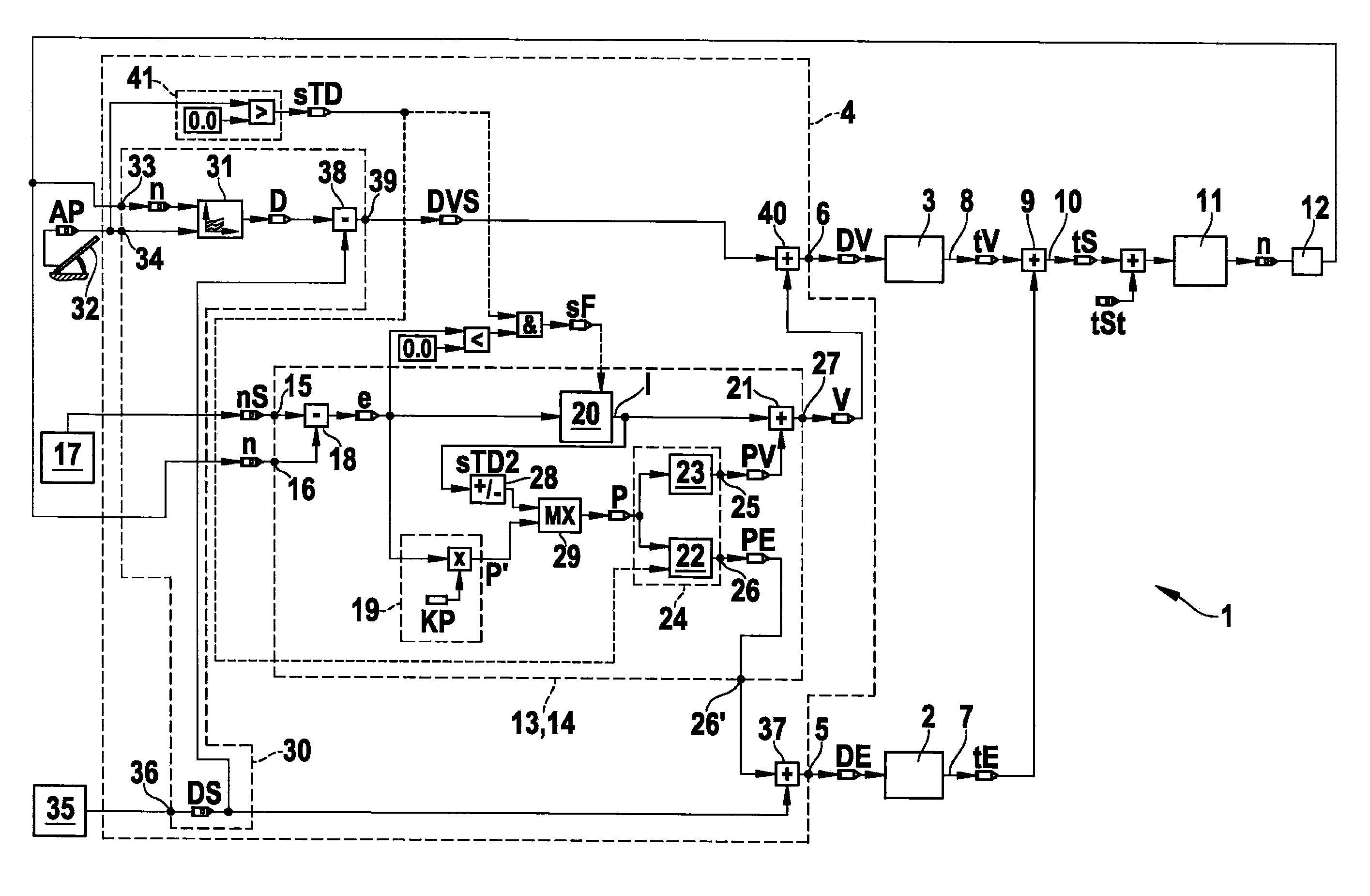
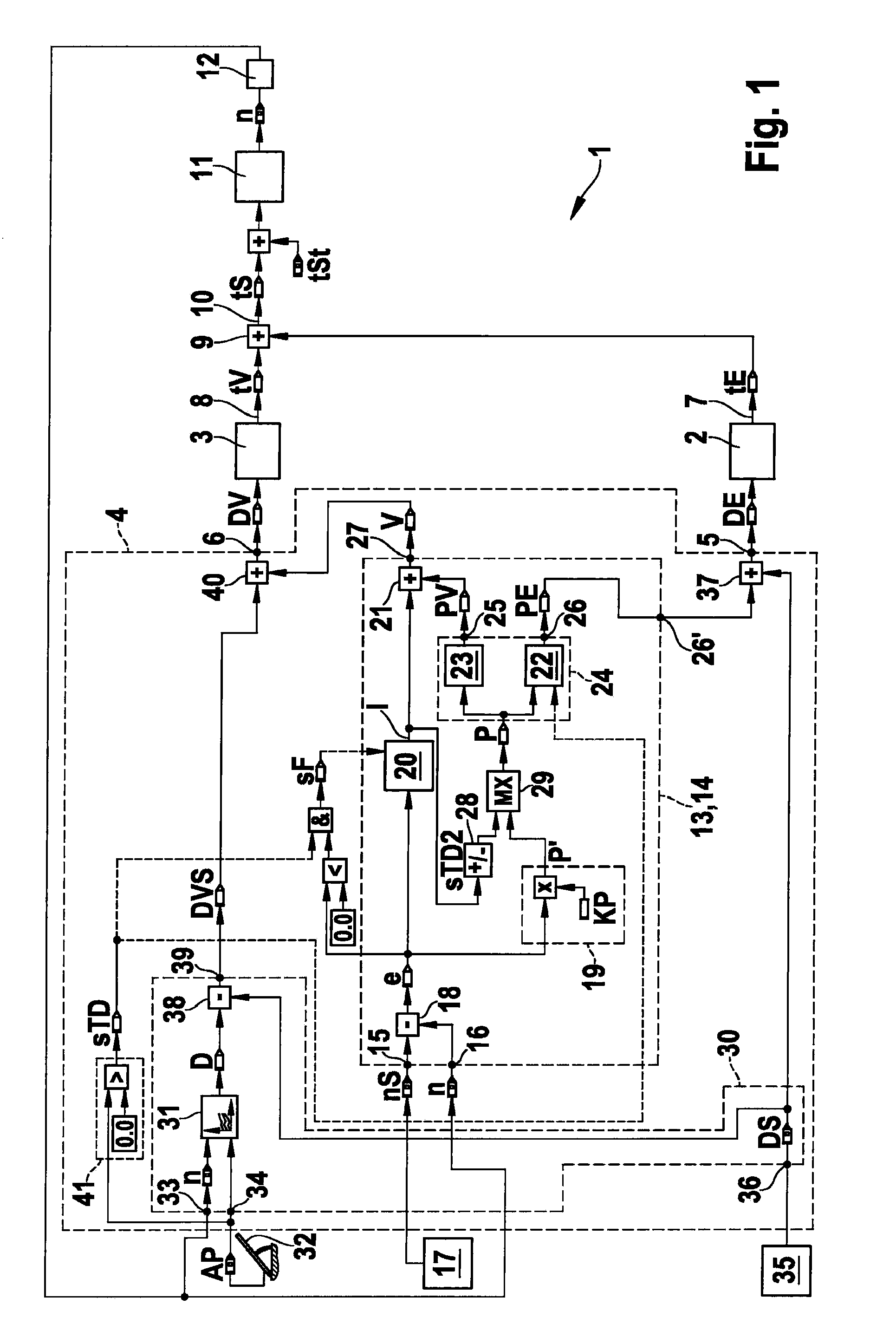
[0023]FIG. 1 shows a block diagram of a simulation of a hybrid drive 1 having two driving motors, the first driving motor being designed as electric motor 2 and the second driving motor as combustion engine 3. Driving motors 2, 3 are driven by a control device 4 which, via an output 5, outputs a first actuating signal DE to electric motor 2 and, via output 6, outputs a second actuating signal DV to combustion engine 3. Driving motors 2, 3 each have an output shaft 7, 8, output shaft 8 of combustion engine 3 and output shaft 7 of electric motor 2 being coupled to one another via a gear unit 9. In this context, added together, electric motor torque tE and combustion engine torque tV form an output torque tS of hybrid drive 1. Connected to gear unit 9 is a common output shaft 10 of driving motors 2, 3 of hybrid drive 1. Output shaft 10 is connected to a mechanical drive unit 11 which is composed, for example, of a differential gear and the driven wheels of a motor vehicle. At mechanica...


PUM


Abstract

A control device for a hybrid drive, in particular for a hybrid drive of a motor vehicle having at least one combustion engine and at least one electric motor as driving motors, whose torques are coupled together to form a total torque. A controller is provided which generates an actuating signal for controlling the speed of each of the driving motors, a first actuating signal acting on the electric motor having a higher dynamic response than a second actuating signal acting on the combustion engine.

Description

FIELD OF THE INVENTION[0001]The present invention relates to a control device for a hybrid drive, in particular for a hybrid drive of a motor vehicle having at least one combustion engine and at least one electric motor as driving motors, whose torques are coupled together to form a total torque.BACKGROUND INFORMATION[0002]Control devices of the type mentioned at the outset are generally known. In this context, control functions and control algorithms are used which produce manipulated variables for the driving motors from a speed of the hybrid drive and a torque demand, for example. In the case of an open-loop / closed-loop control of the speed of the hybrid drive, the control device must apportion the torque demand between the electric motor and the combustion engine. If the driving motors are controlled in parallel, a torque reserve must remain for each of them to allow a rapid torque build-up and a fast reaction to load changes in response to a torque demand. The torque reserve of...

Claims


Application Information

Patent Timeline
Patent Type & Authority Applications(United States)
IPC IPC(8): B60W20/00B60W10/06B60W10/08B60L50/16
CPCB60W10/06B60W10/08Y02T10/6286G05B11/42B60W20/102B60W2050/001B60W2050/0011B60W20/11Y02T10/62B60W20/00
Inventor FALKENSTEIN, JENS-WERNER
Owner ROBERT BOSCH GMBH
Why Eureka
Try Eureka