Low shock strength propulsion system

a propulsion system and shock strength technology, applied in marine propulsion, vessel construction, composite engine plants, etc., can solve the problems of affecting the viability of conventional external compression inlets at high supersonic mach numbers, generating strong shocks off the supersonic inlet and the body of the nacelle, and causing localized interference drag

Active Publication Date: 2010-02-25
GULFSTREAM AEROSPACE CORP
View PDF99 Cites 45 Cited by
  • Summary
  • Abstract
  • Description
  • Claims
  • Application Information

AI Technical Summary

Problems solved by technology

Unfortunately, the traditional nacelle design for a supersonic engine configuration often generates strong shocks off the supersonic inlet and from the body of the nacelle.
These shock waves can also propagate into the aircraft surface, creating localized regions of interference drag.
This adverse trend is a key reason why conventional external compression inlets lose viability at high supersonic Mach numbers.
Unfortunately, these shock waves combine with those from the airframe to create a louder overall sonic boom signature and more interference drag between the nacelle and the remainder of the vehicle.
The stronger the shock waves, the more difficult they become to control and attenuate and the more likely they are to produce additional drag and sonic boom noise.
Problems with this method include the aircraft integration challenges created by the 3-D geometry, such as the fact that the cross-sectional shape may be more difficult to integrate from a packaging perspective compared to an equivalent axisymmetric design for podded propulsion systems.
In addition, the complex inlet shape is likely to create complex distortion patterns that require either large scale mitigating techniques in the subsonic diffuser or the use of engines with more robust operability characteristics.
In addition, increasing the terminal shock Mach number at the base of the shock also encounters significant limitations in practice due to viscous flow effects.
Additionally, the increase in terminal shock Mach number will most likely require complex boundary layer management or a complex inlet control system.
Theoretically, a traditional isentropic compression surface can have better pressure recovery than a straight surface designed to the same operating conditions, but real viscous effects can reduce the overall performance of the isentropic surface inlets and result in poorer boundary layer health.
Moreover, the non-optimal matching between the intake area and the maximum nacelle diameter creates a large forward cowling profile that results in high drag and strong shock generation.
Likewise, the non-optimal matching between exhaust area and maximum nacelle diameter causes a large nozzle boat tail angle, resulting in high drag and strong expansion and re-shock.
While such performance may be acceptable for military aircraft or other such applications, the generation of strong sonic booms in the civil aviation arena is undesirable.

Method used


Image

  • Low shock strength propulsion system
  • Low shock strength propulsion system
  • Low shock strength propulsion system

Examples


Embodiment Construction

[0046]The present disclosure will now be described more fully with reference to the Figures in which various embodiments of the invention are shown. The subject matter of this disclosure may, however, be embodied in many different forms and should not be construed as being limited to the embodiments set forth herein.

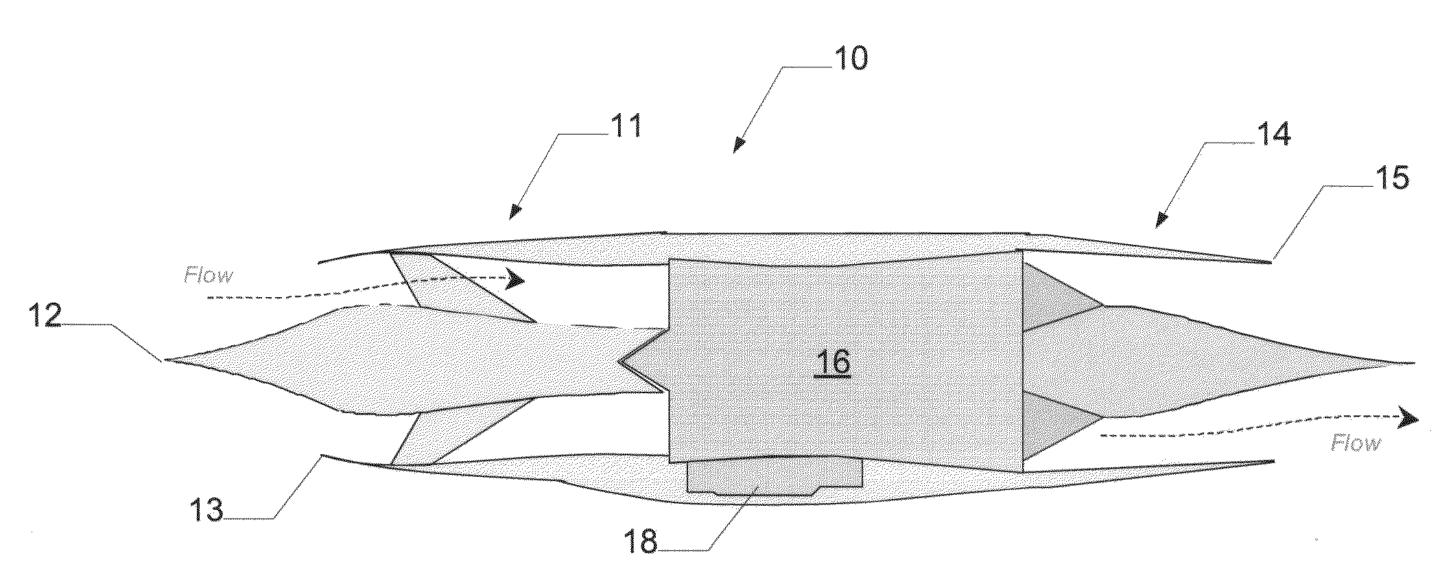
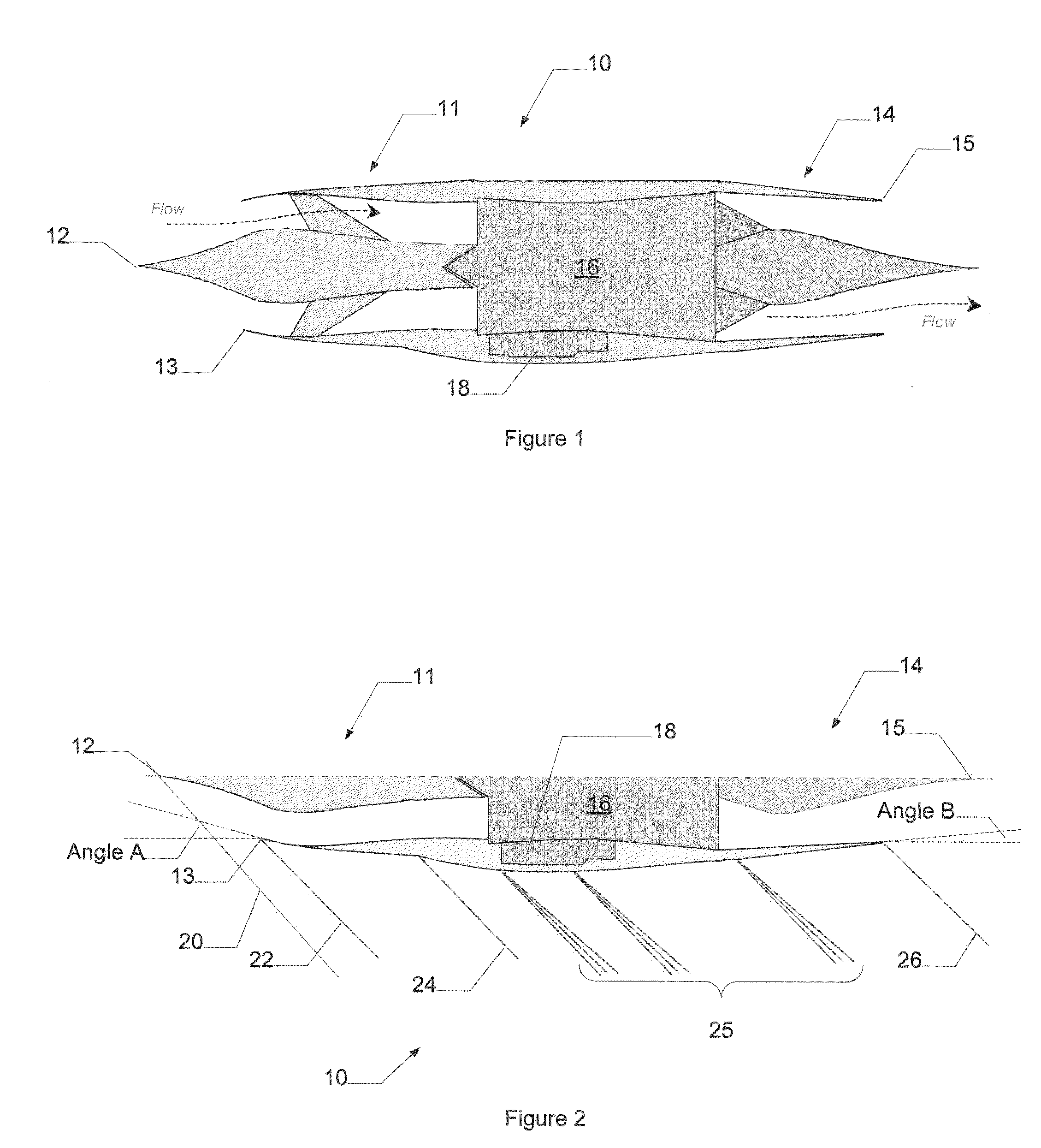
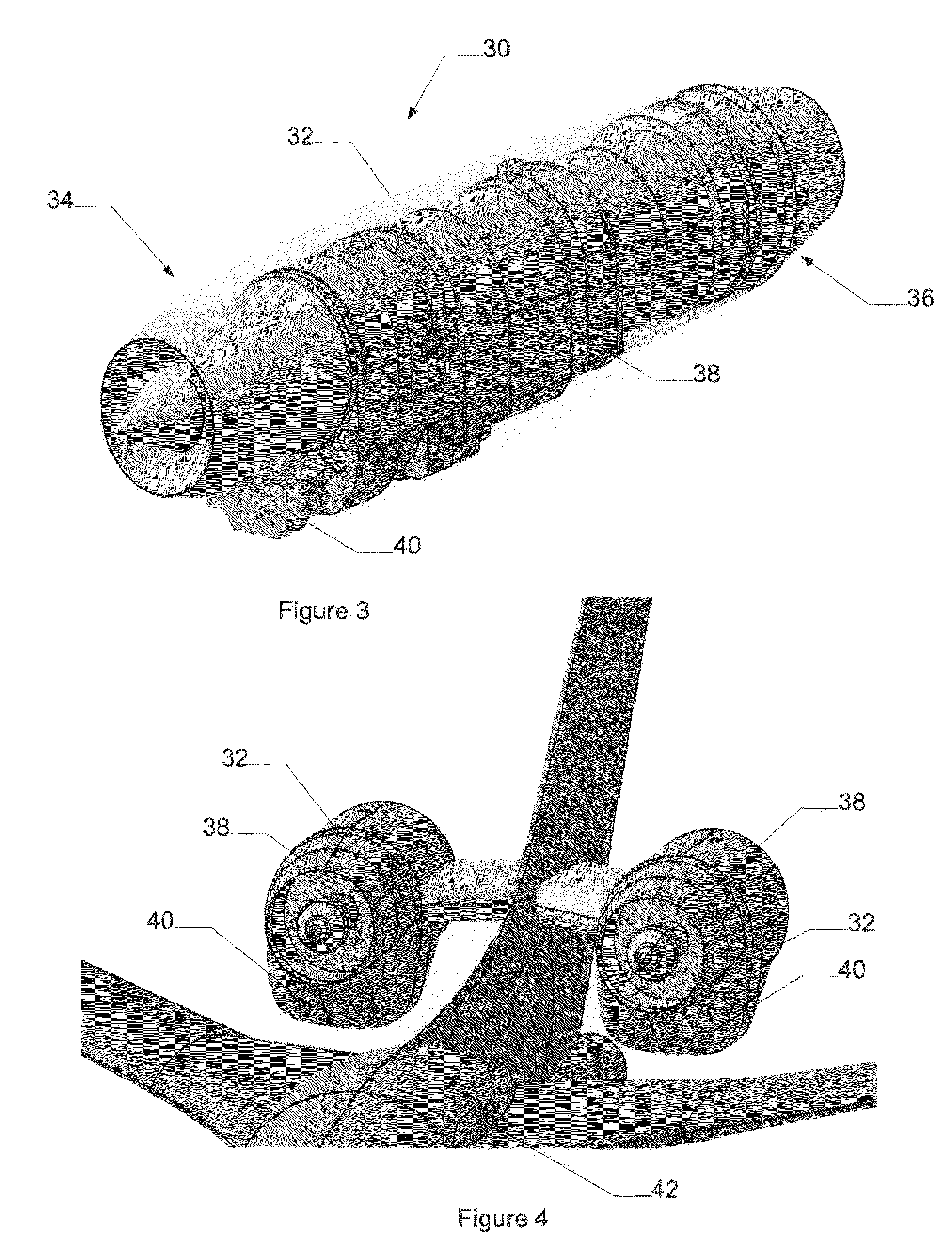
[0047]Embodiments of the invention relate to supersonic nacelle and engine configurations that include a bypass flow around the engine. Design considerations may be used when employing a nacelle incorporating a bypass flow around the engine. For example, an expanded design space may include sonic boom impact, cowl drag, airframe interference drag, subsystem complexity, and alternative structural design techniques, all of which may be optimized against a propulsion system configuration that favors a more streamlined, albeit enlarged, nacelle shape. Growing the forward cowling diameter to better streamline the forward nacelle results in additional captured airflow that can...


PUM


Abstract

Embodiments of the invention relate to a supersonic nacelle design employing a bypass flow path internal to the nacelle and around the engine. By shaping the nacelle, embodiments of the invention may function to reduce sonic boom strength, cowl drag, and / or airframe interference drag. Embodiments of the invention may also function to improve total pressure recovery and / or total thrust of the primary flow path through the engine.

Description

[0001]This application claims priority to co-pending U.S. Provisional Patent Application 60 / 960,986, filed Oct. 24, 2007 and entitled “Supersonic Nacelle,” and U.S. Non-Provisional patent application Ser. No. 12 / 000,066, filed Dec. 7, 2007 and entitled “Low Shock Strength Inlet,” which are hereby incorporated by reference in their entirety and are commonly owned by the assignee.FIELD OF THE INVENTION[0002]Embodiments of the invention are related to supersonic inlets and nozzles for supersonic engines and more particularly to supersonic inlets and nozzles configured with a bypass for reduced sonic boom strength.BACKGROUND OF THE INVENTION[0003]Many supersonic aircraft employ gas turbine engines that are capable of propelling the aircraft at supersonic speeds. These gas turbine engines, however, generally operate on subsonic flow in a range of about Mach 0.3 to 0.6 at the upstream face of the engine. In supersonic applications, a nacelle is used to encompass the engine and incorporate...

Claims


Application Information

Patent Timeline
Patent Type & Authority Applications(United States)
IPC IPC(8): B64G1/40F02K99/00
CPCB64D33/02B64D2033/026F02C7/042Y02T50/672F02C7/045F05D2220/80F02K7/16Y10T137/0536Y10T137/0368F02K3/025Y02T50/60B64D29/00B64D33/06B64D2033/0273
Inventor CONNERS, TIMOTHY R.
Owner GULFSTREAM AEROSPACE CORP
Why Eureka
Try Eureka