Catalyst temperature increasing apparatus for hybrid vehicle

a technology of temperature increasing apparatus and catalyst, which is applied in the direction of machines/engines, propulsion parts, process and machine control, etc., can solve the problem that the purification mechanism of the exhaust gas of the internal combustion engine cannot satisfactorily purify the exhaust gas, and achieve the effect of increasing the amount of heat generated in the electric equipment, increasing the heat generation quantity in the power module, and low efficiency

Active Publication Date: 2010-02-25
TOYOTA JIDOSHA KK
View PDF5 Cites 23 Cited by
  • Summary
  • Abstract
  • Description
  • Claims
  • Application Information

AI Technical Summary

Benefits of technology

[0027]According to the seventh aspect, the electric equipment is operated with a low efficiency when it is determined that the catalyst need be warmed up. Therefore, the amount of heat generated in the electric equipment is increased. As a consequence, the heat generation quantity in the power module is further increased, thus speedily increasing the temperature of the catalyst purifying mechanism with the heat generated in the power module.

Problems solved by technology

According to the first aspect, the catalyst purifying mechanism for purifying the exhaust gas in the internal combustion engine cannot satisfactorily purify the exhaust gas at temperatures of a catalyst activation temperature or lower.
In such a case, when, in particular, a high load is required in the internal combustion engine immediately after the start, much exhaust gas is discharged to the atmosphere while it remains not sufficiently purified when the temperature of the catalyst purifying mechanism remains at the activation temperature or lower.

Method used


Image

  • Catalyst temperature increasing apparatus for hybrid vehicle
  • Catalyst temperature increasing apparatus for hybrid vehicle
  • Catalyst temperature increasing apparatus for hybrid vehicle

Examples


Embodiment Construction

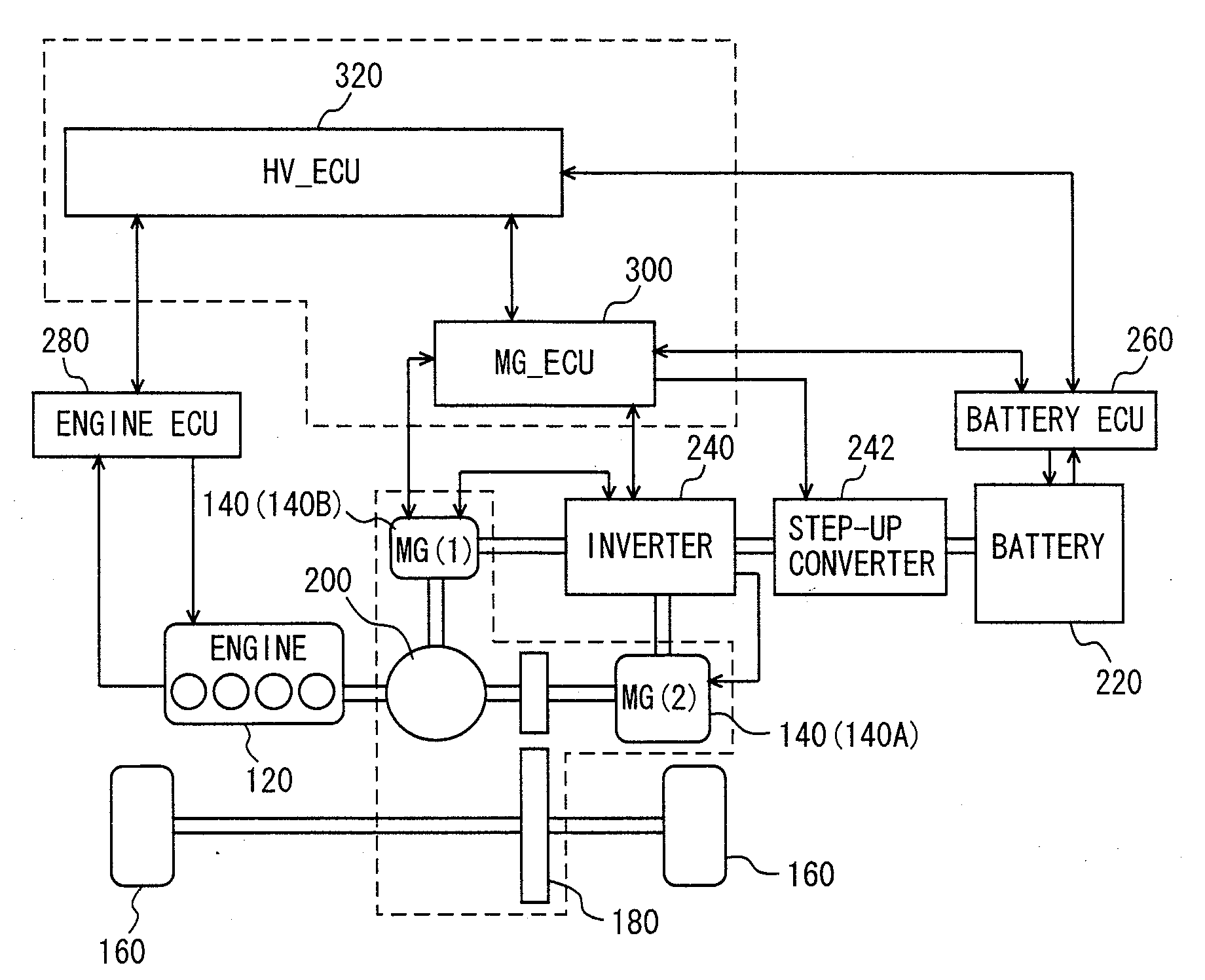
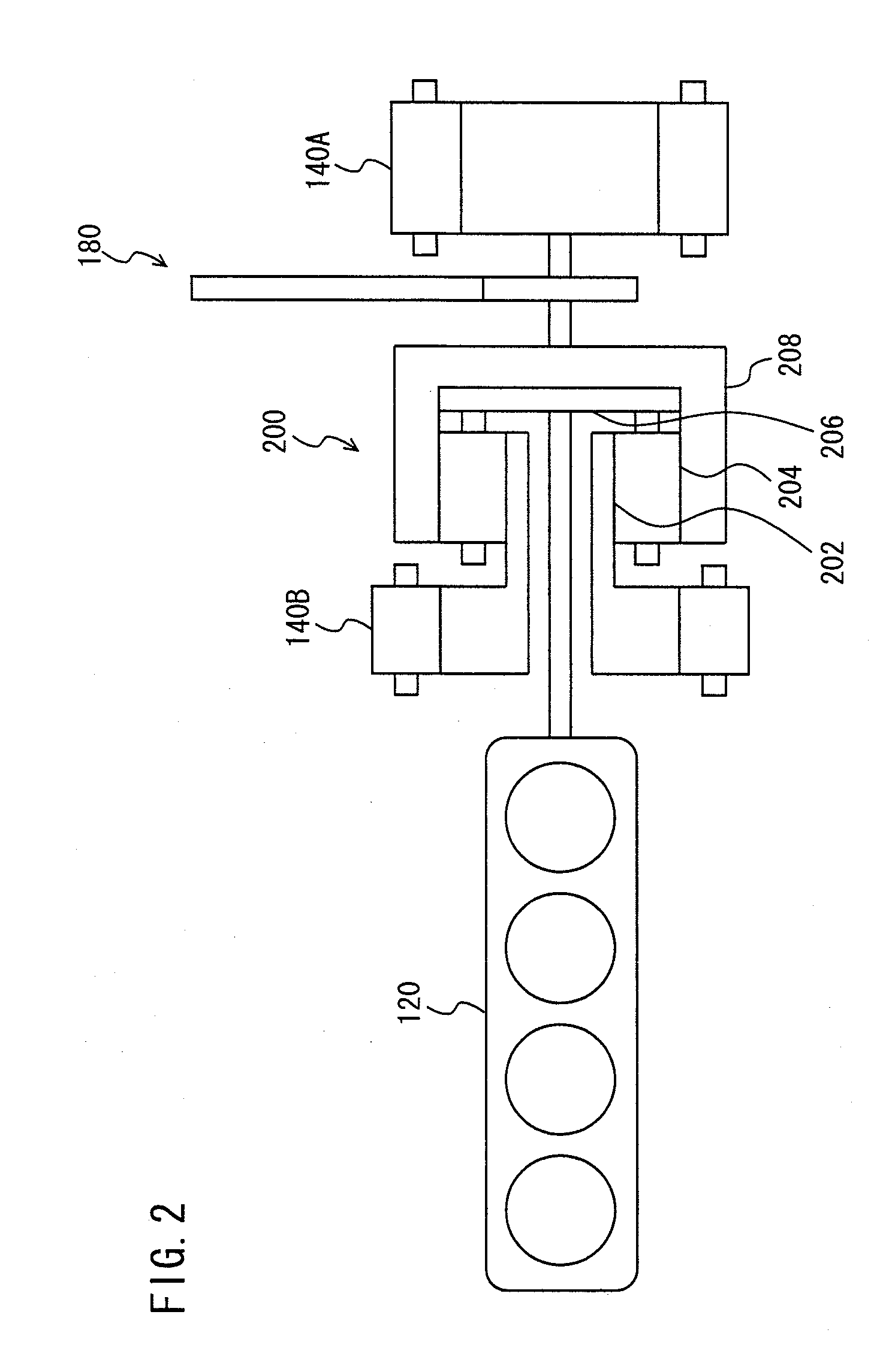
[0033]Referring to the attached drawings, a description will be given below of a preferred embodiment according to the present invention. In the description below, the same component parts are designated by the same reference sign whose names and functions are the same. Therefore, their detailed description will not be repeated below. Incidentally, although the description is given to an engine provided with two three-way catalyst converters in the description below, the present invention is applicable to any engine provided with one or more three-way catalyst converters. In addition, a hybrid system is not limited as long as a vehicle is provided with a power module which generates heat (conversely, which need be cooled).

[0034]Referring to FIG. 1, a description will be given of a control block diagram illustrating a hybrid vehicle as a whole including a catalyst temperature increasing apparatus according to a preferred embodiment of the present invention. Incidentally, the present ...


PUM

PropertyMeasurementUnit
temperatureaaaaaaaaaa
voltageaaaaaaaaaa
voltageaaaaaaaaaa

Abstract

An ECU executes a program including: detecting a catalyst temperature T upon start of an engine; outputting an instruction signal to drive a power module, which is disposed in contact with an outer surface of a catalyst and is high in heat resistance, with a low efficiency upon determination that the catalyst temperature need be increased; and outputting a valve opening instruction signal to a switch valve in a cooling system in such a manner as not to allow a coolant to flow in a coolant pipeline interposed between the power module and an electric part low in heat resistance.

Description

TECHNICAL FIELD[0001]The present invention relates to a catalyst for an engine mounted on a hybrid vehicle and, more particularly, to a technique for effectively utilizing heat in a power module mounted on a hybrid vehicle so as to avoid any degradation of exhaust gas emission.BACKGROUND ART[0002]An exhaust gas system for an engine is generally provided with a catalyst converter for purifying specified components contained in exhaust gas. As such a catalyst converter is widely used a three-way catalyst converter for, with respect to specified three components contained in the exhaust gas, oxidizing carbon oxide (CO) and unburned hydrocarbon (HC) and reducing nitride oxide (NOx), so as to convert the components into carbon dioxide (CO2), water vapor (H2O), and nitrogen (N2), respectively.[0003]A catalyst included in the three-way catalyst converter is degraded in function at low temperatures. Therefore, the catalyst is unsatisfactorily burned unless the temperature of the catalyst is...

Claims


Application Information

Patent Timeline
Patent Type & Authority Applications(United States)
IPC IPC(8): F01N3/20G06F19/00B01D53/94B01J35/02B60K6/445B60W10/06B60W10/08B60W20/00F01N3/24
CPCB60K1/02B60K6/365B60K6/445B60L2240/445B60W10/06B60W20/00F01N13/009F01N3/043F01N3/2006F01N3/2013Y02T10/6239Y02T10/26B60W2510/068Y02A50/20Y02T10/12Y02T10/62B60W2530/12B60W20/15
Inventor HIROSE, SATOSHI
Owner TOYOTA JIDOSHA KK
Why Eureka
Try Eureka