Power transmission mechanism and exhaust heat recovery apparatus

a technology of transmission mechanism and heat recovery apparatus, which is applied in the direction of machines/engines, electrostatic holding devices, transportation and packaging, etc., can solve the problems of increasing friction loss and the problem is yet to be solved, and achieve the effect of reducing friction loss

Inactive Publication Date: 2010-02-25
TOYOTA JIDOSHA KK
View PDF13 Cites 10 Cited by
  • Summary
  • Abstract
  • Description
  • Claims
  • Application Information

AI Technical Summary

Benefits of technology

[0018]With the power transmission mechanism and the exhaust heat recovery apparatus according to the above-described aspec

Problems solved by technology

If the sealing performance improves, however, a sliding resistance between a power transmission shaft and the seal also increases, resulting in an increase of

Method used


Image

  • Power transmission mechanism and exhaust heat recovery apparatus
  • Power transmission mechanism and exhaust heat recovery apparatus
  • Power transmission mechanism and exhaust heat recovery apparatus

Examples


Embodiment Construction

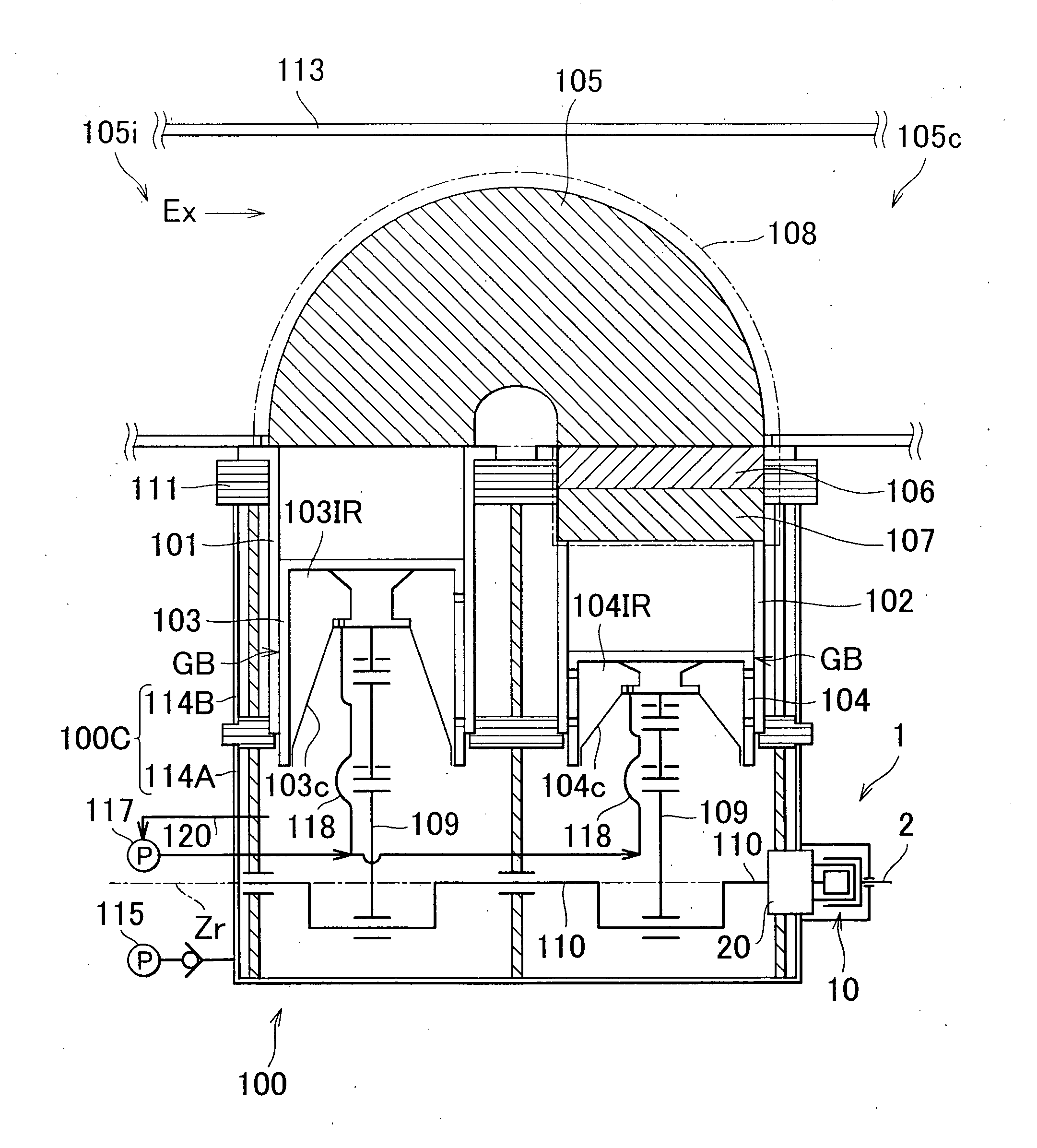
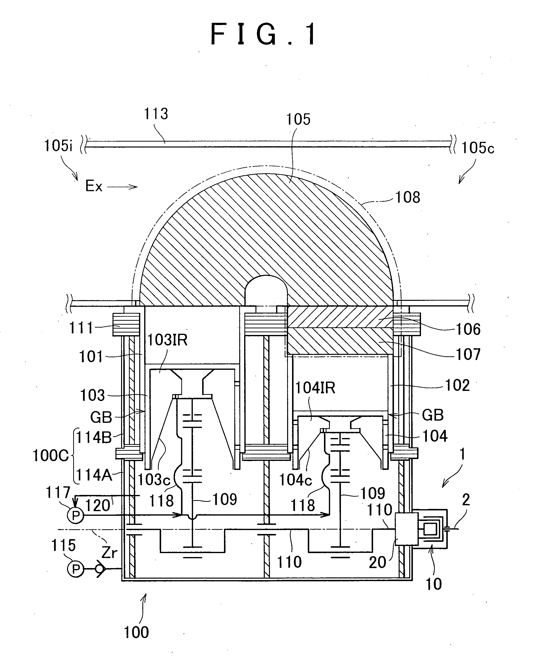
[0029]An example embodiment of the invention will be described with reference to the accompanying drawings. Note that the invention is not limited to the example embodiment described below. Some components described in the following embodiment are readily conceived by those who are skilled in the art or substantially identical with conventional ones. The following description will be provided concerning a situation where a Stirling engine, which is an external combustions engine, is used as a power generation unit and an exhaust heat recovery apparatus, and heat energy is recovered from the exhaust gas discharged from an internal combustion engine, which is a heat engine. Instead of the Stirling engine, an external combustion engine that uses a Brayton cycle may also be used as a power generation unit and an exhaust heat recovery apparatus. Further, the types of heat engines from which exhaust heat is recovered are not particularly limited.

[0030]The example embodiment of the inventi...


PUM


Abstract

A power transmission mechanism that transfers power from an output shaft disposed in sealed-off space within a power generation unit includes: a drive shaft to which the power from the output shaft is transmitted; a first magnet that is fitted to the drive shaft and that rotates together with the drive shaft; a second magnet that is fitted to a driven shaft, which is arranged concentrically with the drive shaft, that is disposed outside the sealed-off space, and that faces the first magnet; and a partition wall that is interposed between the first magnet and the second magnet, and that separates a drive shaft side space and a driven shaft side space from each other.

Description

BACKGROUND OF THE INVENTION[0001]1. Field of Invention[0002]The invention relates to a power transmission mechanism that transfers power from an output shaft disposed in a sealed-off space to the outside of the sealed-off space, and an exhaust heat recovery apparatus that uses the power transmission mechanism.[0003]2. Description of Related Art[0004]There is an exhaust heat recovery apparatus that recovers, by using a heat engine, exhaust heat of an internal combustion engine mounted in a vehicle, for example, an automobile, a bus, or a truck. An example of such exhaust heat recovery apparatus is an external combustion engine, for example, a Stirling engine, which has excellent theoretical thermal efficiency. Japanese Patent Application Publication No. 2005-351242 (JP-A-2005-351242) and Japanese Patent Application Publication No. 2005-351243 (JP-A-2005-351243) each describe a Stirling engine for recovering exhaust heat. The Stirling engine has a hermetically sealed crankcase, and th...

Claims


Application Information

Patent Timeline
IPC IPC(8): F02G5/02F16D27/02
CPCF02G2270/95F02G2280/70H02K5/10Y10T464/30H02K7/1815H02K49/106H02K49/108H02K7/116
Inventor SAWADA, DAISAKUYAGUCHI, HIROSHI
Owner TOYOTA JIDOSHA KK
Why Eureka
Try Eureka