
Cavitation Phase Separators for Steam-Based Generating Systems

a technology of cavitation phase and generating system, which is applied in the direction of liquid degasification, separation process, auxillary pretreatment, etc., can solve the problem of low power recovery of geothermal fluid constituents for reuse, and achieve the effect of optimizing efficiency

Inactive Publication Date: 2010-02-25
CANYON WEST ENERGY
View PDF26 Cites 5 Cited by
  • Summary
  • Abstract
  • Description
  • Claims
  • Application Information

AI Technical Summary

Benefits of technology

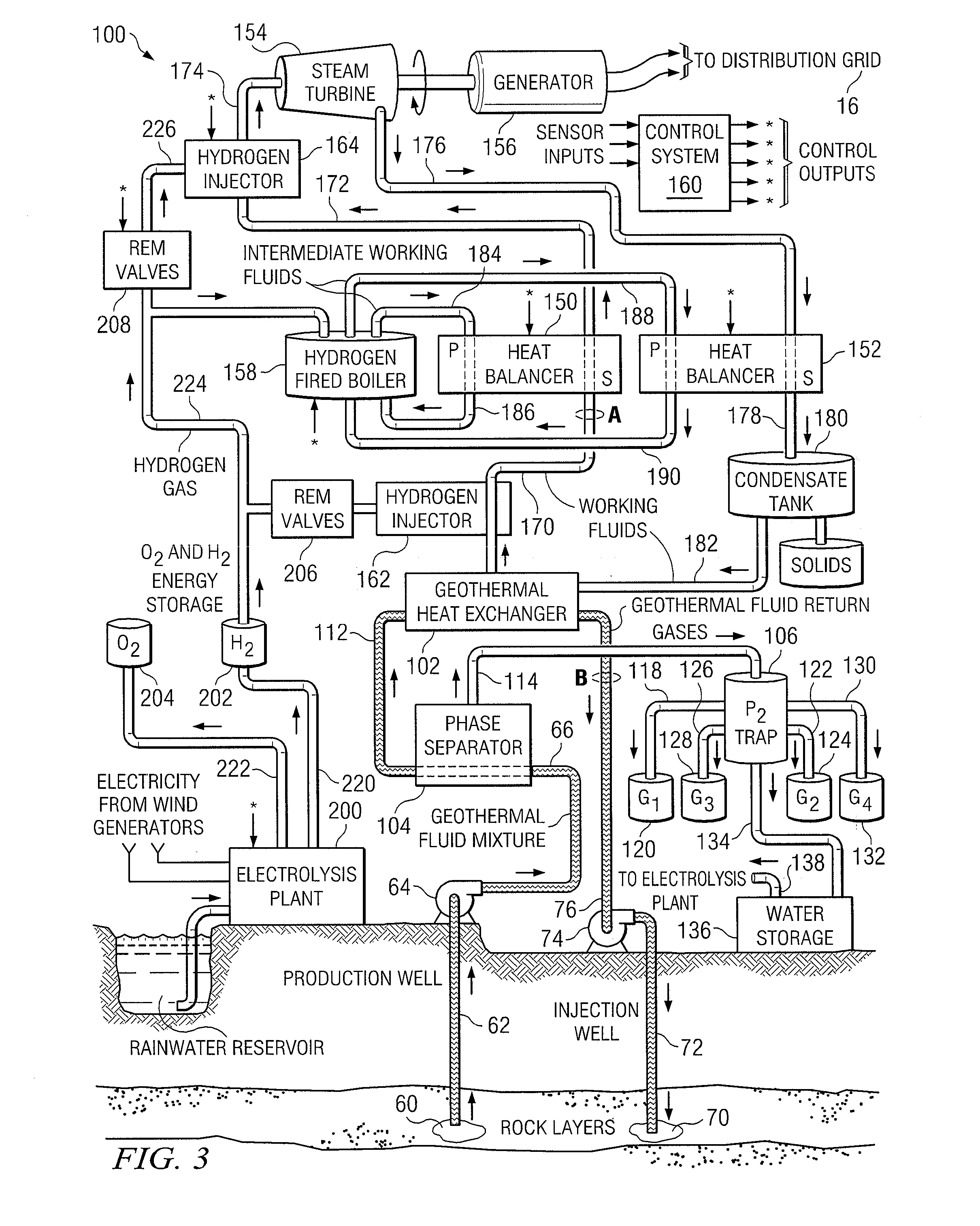
[0014]Accordingly, there are disclosed herein a system, apparatus and methods for the generation of electricity from geothermal, wind power, and other renewable energy resources as supplemented by hydrogen injection and heat balancing to optimize efficiency. In the present invention, hydrogen gas plays a key role in the heat balancing techniques. Further, the system may provide low power recovery of geothermal fluid constituents for reuse, all while operating with minimal or zero atmospheric emissions and ground water pollution.

Problems solved by technology

Further, the system may provide low power recovery of geothermal fluid constituents for reuse, all while operating with minimal or zero atmospheric emissions and ground water pollution.

Method used


Image

  • Cavitation Phase Separators for Steam-Based Generating Systems
  • Cavitation Phase Separators for Steam-Based Generating Systems
  • Cavitation Phase Separators for Steam-Based Generating Systems

Examples


first embodiment

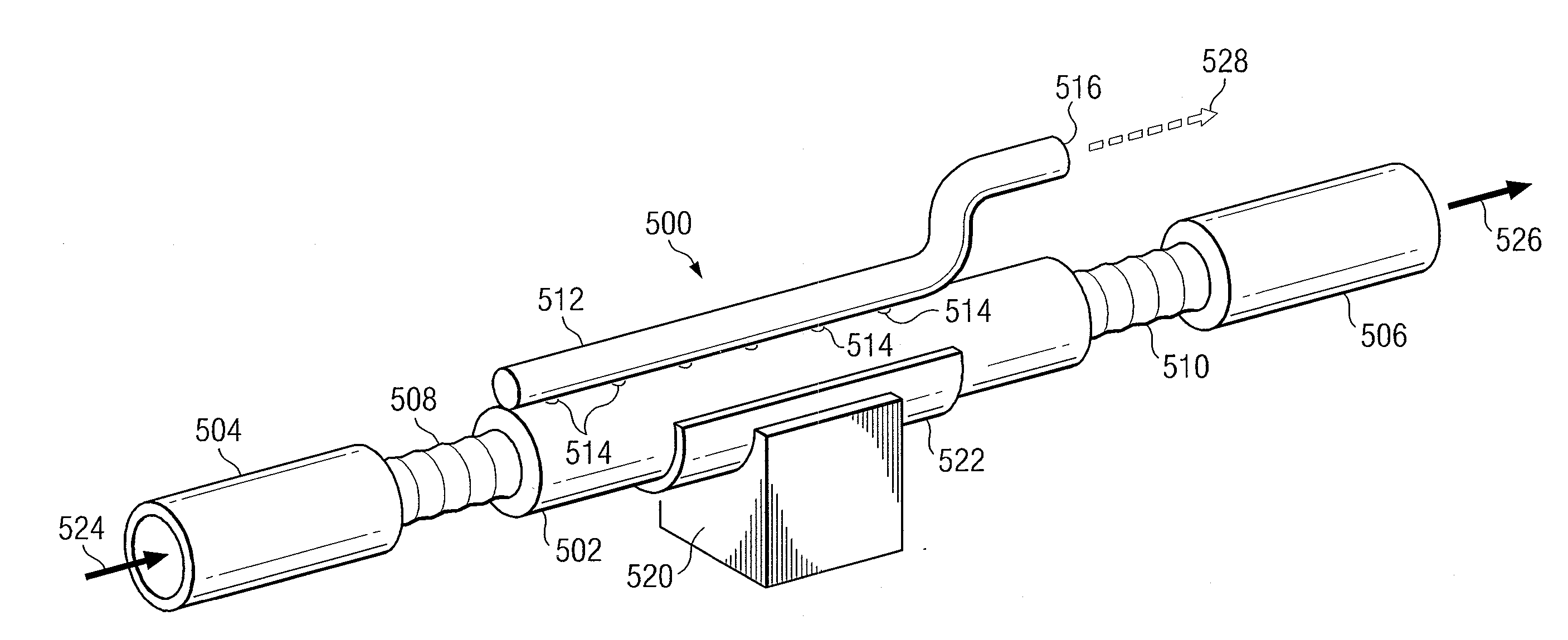
[0122]In the following descriptions of FIGS. 10, 11, 12, and 13, the piezoelectric cavitation phase separator will also be referred to as a “phase separator” or “PCPS,” associated with a reference number in the figure being described. Referring to FIG. 10, there is illustrated a simplified perspective view of a portion of a piezoelectric cavitation phase separator or PCPS 540 according to the present invention. The phase separator 540 in FIG. 10 is called a double-shell resonator and employs a linear piezoelectric stack 570 that may operate in either a 3-3 mode or a 3-1 resonant mode. The cylindrical cavity 544 for this configuration, formed by first 542 and second 546 double-walled “C” sections, includes a slot 572 through the wall of the cavity (from outside to inside diameter), and along each of two opposite sides of the cylinder 544, from end to end, forming two semicircular shells 542, 544 whose concave sides face each other. The two concave, semicircular shells 542, 544 are di...

second embodiment

[0125]Referring to FIG. 12, there is illustrated a simplified perspective view of a portion of a piezoelectric cavitation phase separator according to the present invention. This embodiment 600 of the PCPS may be called in this context a single shell or tuning fork resonator in which a transducer cylinder or body 602 includes a thin piezoelectric layer 606. The transducer cylinder or body 602 is a laminated structure having nested layers including an outer shell 604, the piezoelectric layer 606, and an inner insulating layer 608. The transducer 602, which forms a cylindrical cavity within it, further includes a single slot 640 disposed through the wall of the transducer cylinder or body 602 and the piezoelectric lining from end-to-end, parallel to its longitudinal axis. The single slot 640 in effect defines first 642 and second 644 sides or halves of the cylindrical body 602.

[0126]The piezoelectric layer 606 is driven by an electrical signal applied across the piezoelectric layer th...


PUM

PropertyMeasurementUnit
Temperatureaaaaaaaaaa
Diameteraaaaaaaaaa
Efficiencyaaaaaaaaaa

Abstract

A system, apparatus and method for generating electricity from renewable geothermal, wind, and solar energy sources includes a heat balancer for supplementing and regulating the heat energy fed to a turbine generator; a hydrogen-fired boiler for supplying supplementary heat; and an injection manifold for metering controlled amounts of superheated combustible gas into the working fluids to optimize efficiency.Wind or solar power may be converted to hydrogen in an electrolysis unit to produce hydrogen. A phase separator unit that operates by cavitation of the geothermal fluids removes gases from the source fluid. A pollution prevention trap may be used to remove solids and other unneeded constituents of the geothermal fluids to be stored or processed in a solution mining unit for reuse or sale. Spent geothermal and working fluids may be processed and injected into the geothermal strata to aid in maintaining its temperature or in solution mining of elements in the lithosphere.

Description

CROSS REFERENCE TO RELATED APPLICATIONS[0001]The present U.S. Patent Application is related to the following co-pending U.S. Patent Applications entitled: Renewable Energy Electric Generating System; Heat Balancer for Steam-based Generating Systems, Methods for Enhancing Efficiency of Steam-based Generating Systems; and Steam-based Electric Power Plant Operated on Renewable Energy. The present and foregoing related patent applications claim priority from U.S. Provisional Patent Application No. 61 / 090,092, filed Aug. 19, 2008 and entitled Electric Power Generation System Utilizing Multiple Renewable Energy Resources, by the same inventors.BACKGROUND OF THE INVENTION[0002]1. Field of the Invention[0003]The present invention generally relates to electric power generation using renewable sources of energy, and more particularly to enhanced uses of wind or solar energy in combination with geothermal fluids originating in hot strata of the earth's mantle as a source of heat for operating ...

Claims


Application Information

Patent Timeline
IPC IPC(8): B03C3/40B03C3/66
CPCF24J3/085F28D9/0006Y02E10/725F28F19/02Y02E10/14F28F3/046Y02P20/133F24T10/20Y02E10/10Y02E10/72
Inventor KELLY, PATRICK J.
Owner CANYON WEST ENERGY
Learn More