
Porous Layer

a technology of porous layer and insulating layer, which is applied in the direction of superimposed coating process, lighting and heating apparatus, instruments, etc., can solve the problems of increasing critical heat flux, increasing heat transfer coefficient, and reducing temperature overshoot, so as to increase the thermal conductivity and mechanical stability of the structure.

Inactive Publication Date: 2010-02-25
DANFOSS AS
View PDF10 Cites 32 Cited by
  • Summary
  • Abstract
  • Description
  • Claims
  • Application Information

AI Technical Summary

Benefits of technology

[0019]As used herein, the term “surface” means the part of the heat transfer device in contact with the boiling liquids. The surface layer with both regularly spaced and shaped micron-sized pores and a wall structure of dendritically ordered nanoparticles is applied on to the original surface of the heat transfer device, hence forming an enhanced boiling surface. The original heat transfer surface could be of any geometry such as flat, cylindrical, spherical, fin-structured, etc. and with any surface roughness.
[0022]As used herein, the term “annealing” means the process of heat treatment below the melting temperature of the materials used in order to attain a larger contact between deposited nanoparticles, thus increasing the thermal conductivity and mechanical stability of the structure.

Problems solved by technology

Enhanced surfaces not only increase the heat transfer coefficient but may also increase the critical heat flux (CHF) and decrease the temperature overshoot at boiling incipience.
However, little attention has been paid to the surface modification by nanostrncturing to produce high performance nucleate boiling surfaces.
Those methods are not capable of creating well defined nanostructured surfaces, because of the physical limitations of the mechanical techniques, and are therefore limited to the creation of less well-defined micron-sized features.
Since the structure can only be fabricated on circular geometries, the area of application is limited to boiling on the outside surface of tubes.
The mechanical treatment also prohibits the possibilities for tailor making the nano-features of the structure.
This fabrication technique is restrained to producing randomly sized cavities and with limited possibility to modify the nano-sized features of the structure.
Thus, the structure is not well ordered and it is not possible to tailor make features in the nano-scale to enhance heat transfer in boiling.

Method used


Image

  • Porous Layer
  • Porous Layer
  • Porous Layer

Examples


Embodiment Construction

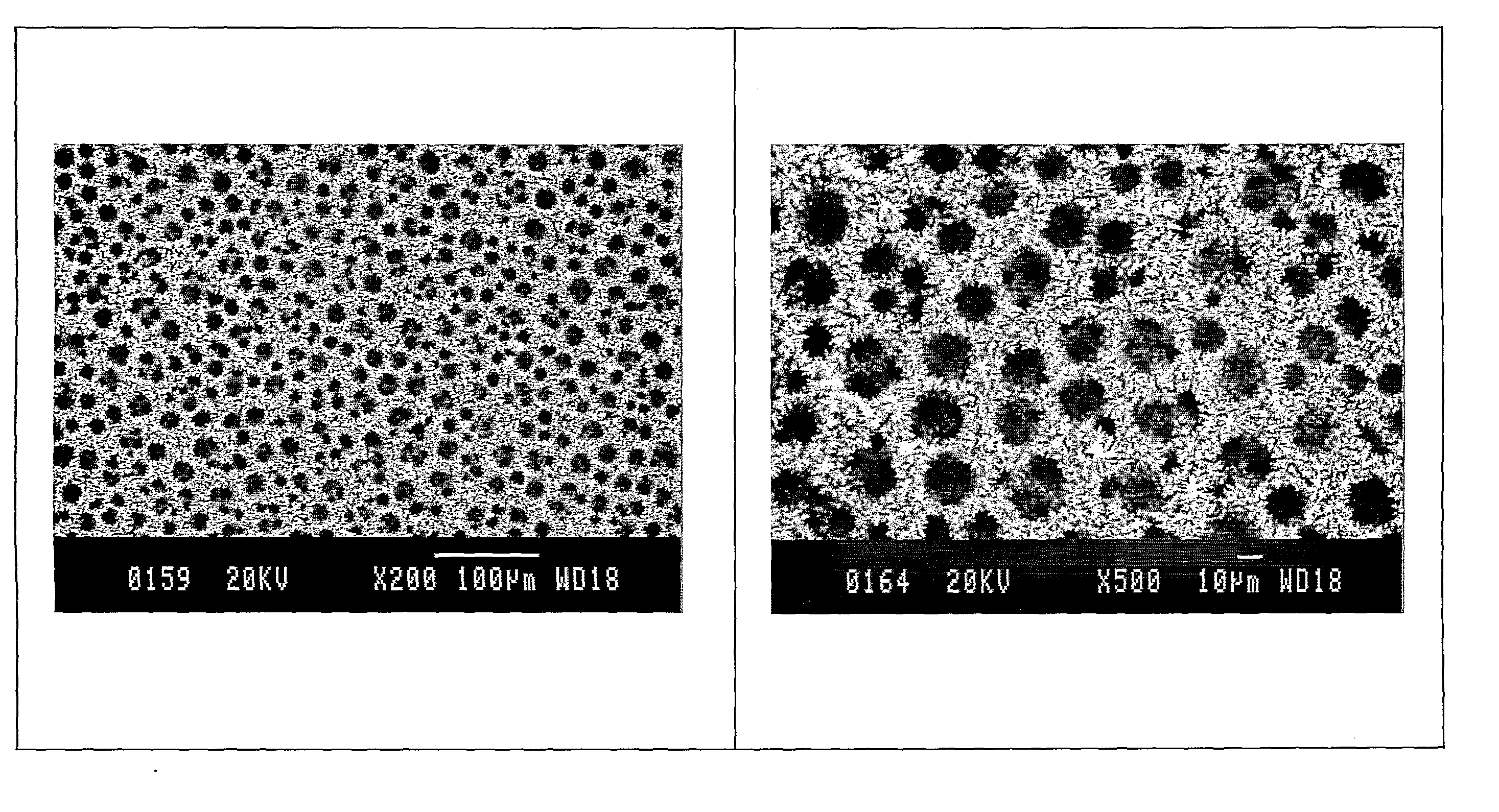
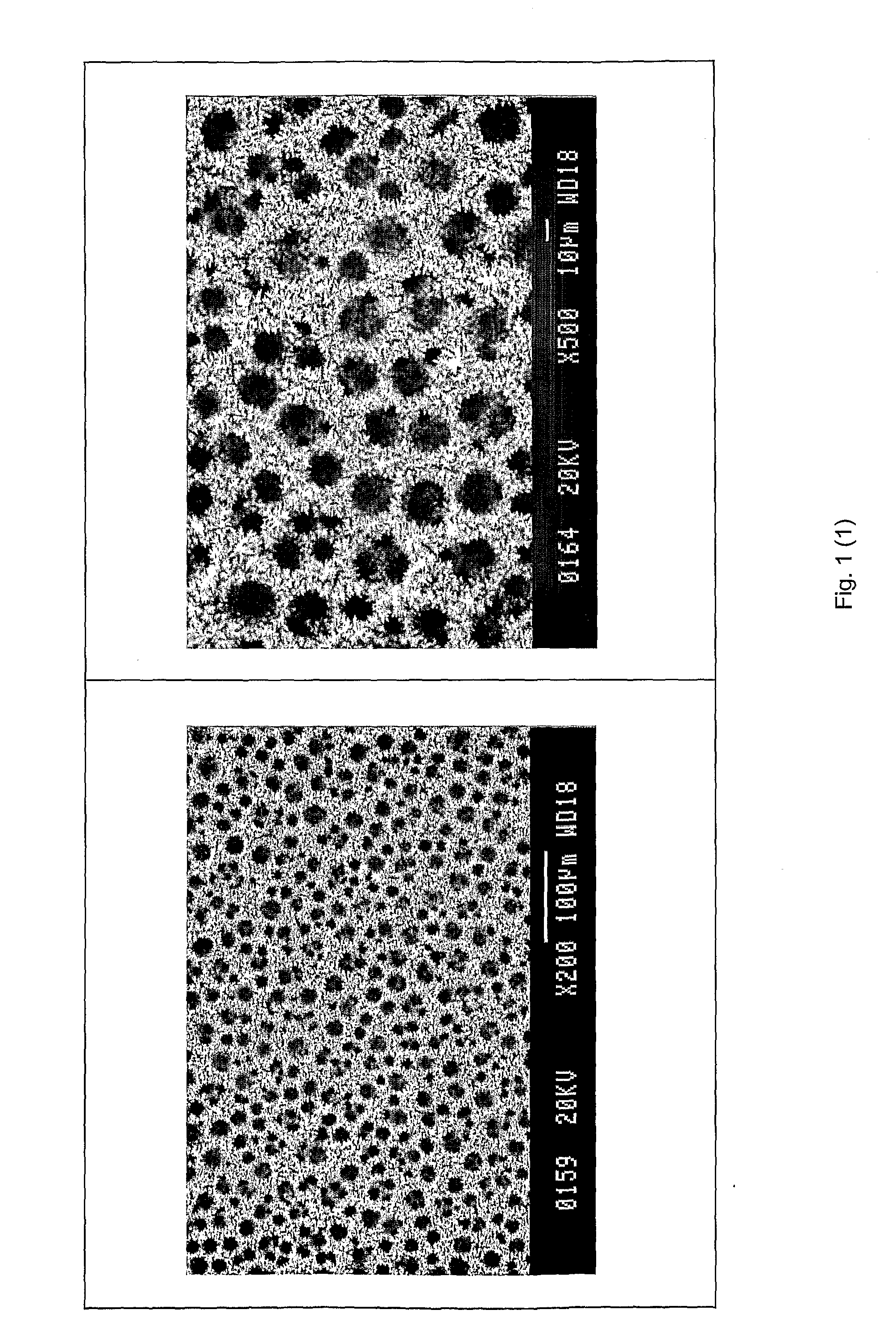
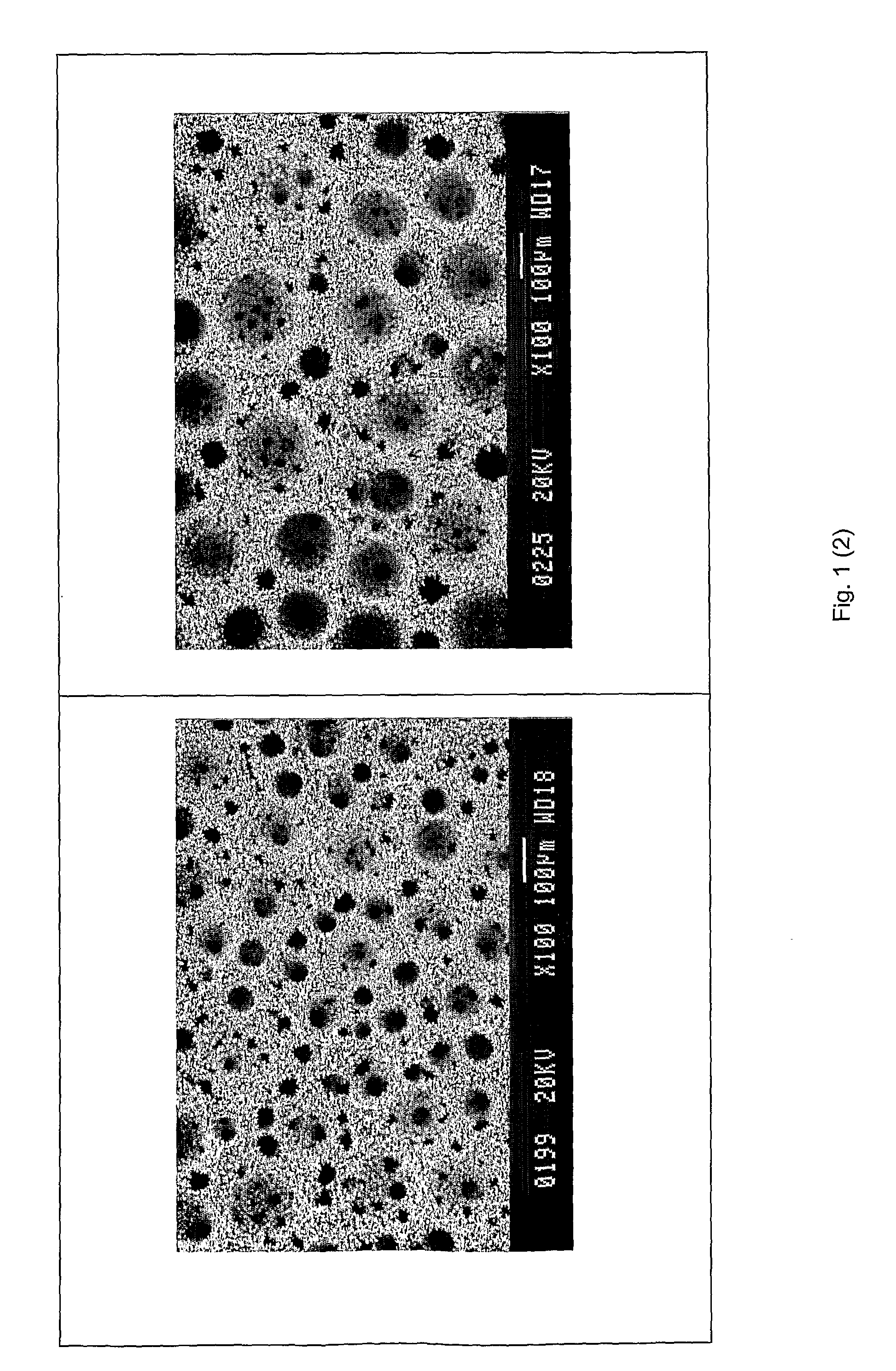
[0035]The porous surface layer according to the present invention comprises both a porous wall structure and regularly spaced and shaped macro-pores separated by and defined by said porous wall structure. The macro-pores are regularly spaced over the surface layer area, regularly sized and shaped, and they are interconnected in the general direction normal to the surface of the substrate and gradually increase in size with distance from the substrate. The porous wall structure is comprised of a rigid continuous branched structure of a suitable thermally conductive material. As may be seen in the explanations to the experimental results, the porous wall structure and the macro-pores both improve the boiling behavior of the surface layer, and the combination results in major advantages over the prior art.

[0036]A surface layer with both regularly spaced and shaped macro-pores that are interconnected in the general direction normal to the surface of the substrate and gradually increase ...


PUM

PropertyMeasurementUnit
diameteraaaaaaaaaa
diameteraaaaaaaaaa
temperatureaaaaaaaaaa

Abstract

Heat exchange device with a boiling surface comprising porous surface layer arranged on a solid substrate, the porous surface layer comprises a porous wall structure defining and separating macro-pores that are interconnected in the general direction normal to the surface of the substrate and have a diameter greater than 5 μm and less than 1000 μm wherein the diameter of the pores gradually increases with distance from the substrate wherein the porous wall structure is a continuous branched structure.

Description

TECHNICAL FIELD[0001]The present invention is directed to a porous layer, a heat exchanger device with a boiling surface with a porous surface layer arranged on a solid substrate, and a method for forming a porous surface layer on a substrate.BACKGROUND OF THE INVENTION[0002]The present invention relates to developing new high-efficiency evaporators. In refrigeration equipment, air conditioning equipment and heat pumps, commonly named heat pumping equipment, it is very important to operate with small temperature differences between the heat source, e.g. air or water, and the boiling refrigerant in the evaporator. These small temperature differences contribute to decrease the difference between the condensation temperature and the evaporation temperature which is very important to achieve high energy efficiency of the system, usually expressed in terms of the coefficient of performance (COP) defined as, for heating purposes, the amount of heat (q1) delivered to the warm side divided ...

Claims


Application Information

Patent Timeline
Patent Type & Authority Applications(United States)
IPC IPC(8): F28F13/18B32B5/00B05D3/02B05D1/36C23C16/00C23C28/02C25D5/00
CPCC25D5/16C25D5/50F28F13/187Y10T428/26C25D5/003F28F2255/20Y10T428/12479C25D7/00C25D5/623C25D5/617C25D5/605
Inventor FURBERG, RICHARDPALM, BJORNLI, SHANGHUAMUHAMMED, MAMOUNTOPRAK, MUHAMMET
Owner DANFOSS AS
Learn More