Earth-boring bits and other parts including cemented carbide

a technology of cemented carbide and earth-boring bits, which is applied in the direction of earth-boring mining, cutting machines, transportation and packaging, etc., can solve the problems of reducing wear resistance, increasing toughness generally accompanied, and limiting the range of compact shapes that can be formed

Active Publication Date: 2010-02-25
KENNAMETAL INC
View PDF38 Cites 55 Cited by
  • Summary
  • Abstract
  • Description
  • Claims
  • Application Information

AI Technical Summary

Problems solved by technology

However, this increase in toughness is generally accompanied by decreased wear resistance.
A significant limitation of press-and-sinter fabrication techniques is that the range of compact shapes that can be formed is rather limited, and the techniques cannot effectively be used to produce complex part shapes.
Whether rigid tooling or flexible tooling is used, however, the consolidated compact must be extracted from the tool, and this limitation limits the compact shapes that can formed.
Since isostatic presses use flexible tooling, however, pressed compacts with precise shapes cannot be formed.
However, the range of shapes that are possible from green shaping is limited.
The possible shapes are limited by the availability and capabilities of the machine tools.
Machine tools that may be used in green machining must be highly wear resistant and are generally expensive.
Also, green machining of compacts used to form cemented carbide parts produces highly abrasive dust.
However, both metallurgical and mechanical joining techniques are deficient because of the inherent properties of cemented carbide and / or the mechanical properties of the joint.
Because typical brazing or welding alloys have strength levels much lower than cemented carbides, brazed and welded joints are likely to be much weaker than the attached cemented carbide pieces.
Also, since the brazing and welding deposits do not include carbides, nitrides, silicides, oxides, borides, or other hard phases, the braze or weld joint also is much less wear resistant than the cemented carbide materials.
Because cemented carbides are relatively brittle materials, they are extremely notch-sensitive, and the stress concentrations associated with mechanical joining features may readily result in premature fracture of the cemented carbide.
Due to the high strength and hardness of sintered cemented carbides, which makes machining the material difficult, the green compact typically is machined to include the features of the bit body, and then the machined compact is sintered.
Thus, earth-boring bits including solid cemented carbide bit bodies may exhibit significantly longer service lifetimes than bits including machined steel or infiltrated hard particle bit bodies.
However, solid cemented carbide earth-boring bits still suffer from some limitations.
For example, it can be difficult to accurately and precisely position the individual PDC cutters on solid cemented carbide bit bodies since the bit bodies experience some size and shape distortion during the high temperature sintering process.
If the PDC cutters are not located precisely at predetermined positions on the bit body blades, the earth-boring bit may not perform satisfactorily due to, for example, premature breakage of the cutters and / or the blades, excessive vibration, and / or drilling holes that are not round (“out-of-round holes”).
However, as discussed hereinabove, even the most sophisticated machine tools can provide only a limited range of shapes and designs.
For example, the number and shape of cutting blades and the PDC cutters mounting positions that may be machined is limited because shape features cannot interfere with the path of the cutting tool during the machining process.

Method used


Image

  • Earth-boring bits and other parts including cemented carbide
  • Earth-boring bits and other parts including cemented carbide
  • Earth-boring bits and other parts including cemented carbide

Examples


example 1

[0100]FIG. 5 is a photograph of a composite article 70 made according to embodiments of a method of the present disclosure. The article 70 includes several individual sintered cemented carbide pieces 72 bonded together by a joining phase 74 comprising hard inorganic particles dispersed in a metallic matrix. The individual sintered cemented carbide pieces 72 were fabricated by conventional techniques. The cemented carbide pieces 72 were positioned in a cylindrical graphite mold, and an unoccupied space was defined between the pieces 72. Cast tungsten carbide particles were placed in the unoccupied space, a remainder space existed between the individual tungsten carbide particles. The mold containing the cemented carbide pieces 72 and the cast tungsten carbide particles was heated to a temperature of 1180° C. A molten bronze was introduced into the void of the mold and infiltrated the remainder space, binding together the cemented carbide pieces and the cast tungsten carbide particles...

example 2

[0102]FIG. 7 is a photograph of an additional composite article 80 made according to embodiments of a method of the present disclosure. Article 80 comprises two sintered cemented carbide pieces 81 bonded in the article 80 by a Ni—WC alloy 82 having a eutectic composition. The article 80 was made by disposing a powder blend consisting of 55% (w / w) nickel powder and 45% (w / w) tungsten carbide powder in a chamfered region between the two cemented carbide pieces 81. The assembly was heated in a vacuum furnace at a temperature of 1350° C. which was above the melting point of the powder blend. The molten material was cooled and solidified in the chamfered region as the Ni—WC alloy 82, bonding together the cemented carbide pieces 81 to form the article 80.

example 3

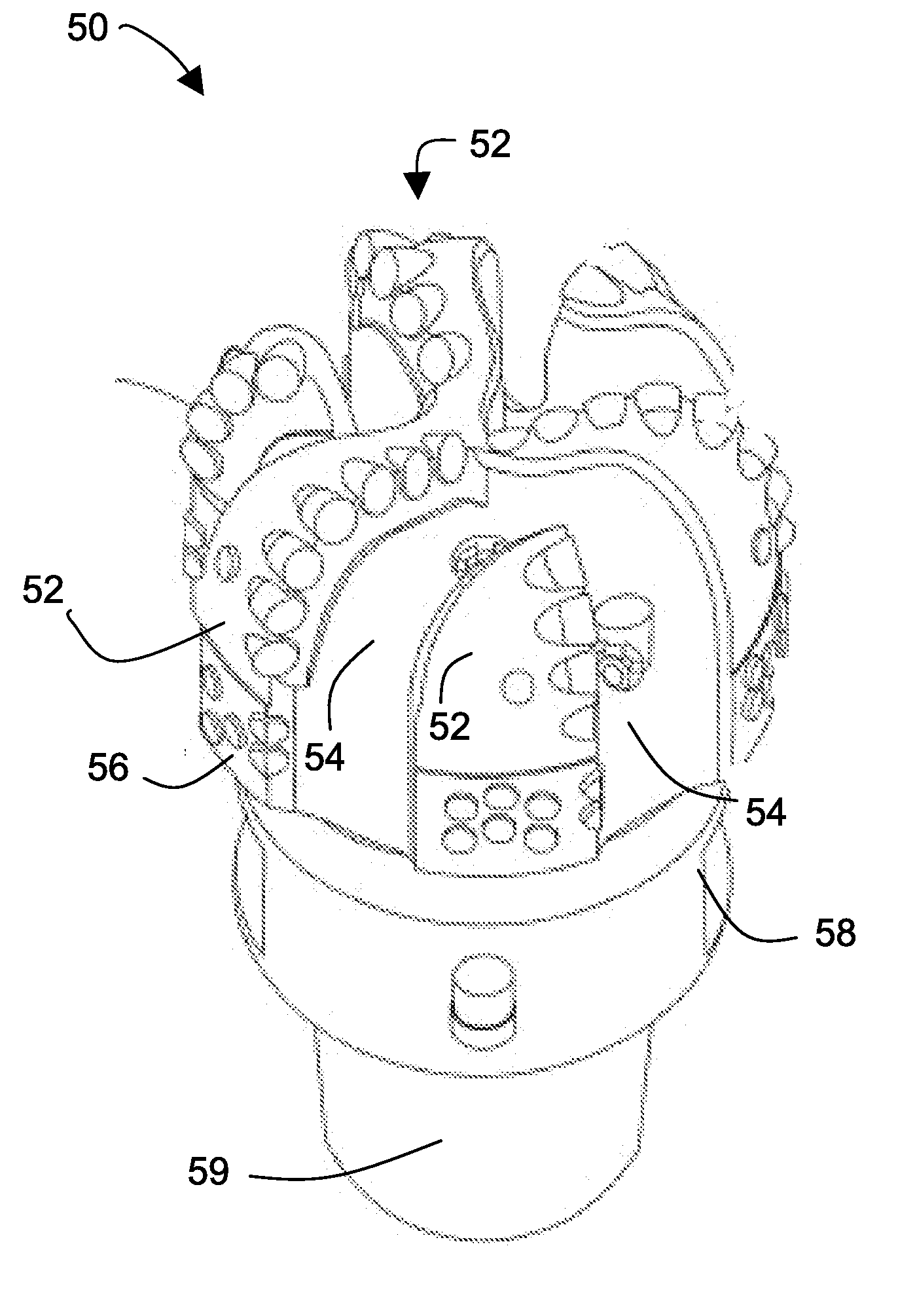
[0103]FIG. 8 is a photograph of a fixed-cutter earth-boring bit 84 according to a non-limiting embodiment according of the present disclosure. The fixed-cutter earth-boring bit 84 includes sintered cemented carbide pieces forming blade regions 85 bound into the bit 84 by a first metallic joining material 86 including cast tungsten carbide particles dispersed in a bronze matrix. Polycrystalline diamond compacts 87 were mounted in insert pockets defined within the sintered cemented carbide pieces forming the blade regions 85. A non-cemented carbide piece also was bonded into the bit 84 by a second metallic joining material and formed a machinable attachment region 88 of the bit 84. The second joining material was a metallic composite including tungsten powder (or grains) dispersed in a bronze casting alloy.

[0104]Referring now to FIGS. 8-12, the fixed-cutter earth-boring bit 84 illustrated in FIG. 8 was fabricated as follows. FIG. 9 is a photograph of sintered cemented carbide pieces 9...


PUM

PropertyMeasurementUnit
weight percentaaaaaaaaaa
temperatureaaaaaaaaaa

Abstract

An article of manufacture includes a cemented carbide piece, and a joining phase that binds the cemented carbide piece into the article. The joining phase includes inorganic particles and a matrix material. The matrix material is a metal and a metallic alloy. The melting temperature of the inorganic particles is higher than the melting temperature of the matrix material. A method includes infiltrating the space between the inorganic particles and the cemented carbide piece with a molten metal or metal alloy followed by solidification of the metal or metal alloy to form an article of manufacture.

Description

BACKGROUND OF THE TECHNOLOGY[0001]1. Field of the Technology[0002]The present disclosure relates to earth-boring articles and other articles of manufacture comprising sintered cemented carbide and to their methods of manufacture. Examples of earth-boring articles encompassed by the present disclosure include, for example, earth-boring bits and earth-boring bit parts such as, for example, fixed-cutter earth-boring bit bodies and roller cones for rotary cone earth-boring bits. The present disclosure further relates to earth-boring bit bodies, roller cones, and other articles of manufacture made using the methods disclosed herein.[0003]2. Description of the Background of the Technology[0004]Cemented carbides are composites of a discontinuous hard metal carbide phase dispersed in a continuous relatively soft binder phase. The dispersed phase, typically, comprises grains of a carbide comprising one or more of the transition metals selected from, for example, titanium, vanadium, chromium,...

Claims


Application Information

Patent Timeline
Patent Type & Authority Applications(United States)
IPC IPC(8): E21B10/00C22C32/00B22D19/14B22D23/06
CPCB22F3/1035B22F3/26B22F2005/001Y10T428/12486E21B10/42Y10T428/12146C22C29/08E21B10/567
Inventor MIRCHANDANI, PRAKASH K.CHANDLER, MORRIS E.WALLER, MICHALE E.COLEMAN, HEATH C.
Owner KENNAMETAL INC
Why Eureka
Try Eureka