Ultrasound liquid atomizer

a liquid atomizer and ultrasonic technology, applied in the field of ultrasonic liquid atomizers, can solve the problems of excessively fast expulsion of aerosol, limitations of conventional devices, etc., and achieve the effects of improving throughput and uniformity performance, enhancing performance, and little effect on vibratory behavior of atomizers

Active Publication Date: 2010-02-25
TELEMAQ SAS
View PDF20 Cites 76 Cited by
  • Summary
  • Abstract
  • Description
  • Claims
  • Application Information

AI Technical Summary

Benefits of technology

[0033]This property enables the atomizer to operate equally at any angle from the vertical to the horizontal. The liquid can also be guided to the membrane by capillarity by using ducts, wicks or appropriate porous materials. In this way, the liquid reservoir can be located above, around or below the atomizer. According to a variant of the invention, the structure of the atomizer comprises a rear mass, also called dynamic mass, the role of which is to prevent the transducer from vibrating backward, two piezoelectric ceramics linked by common connections, a vibratory movement amplifier including a cavity and a micro-perforated membrane of varied shape but preferably dished forming a protuberance or dome.
[0034]According to another variant of the invention, a pre-stressing mechanism like a screw can be used to mechanically link the rear mass, the ceramics and the amplifier. The amplifier is metallic and preferably made of stainless steel, titanium or aluminum. The micro-perforated membrane is glued to the vibratory amplifier. The membrane, which has little effect on the vibratory behavior of the atomizer, can be made of a variety of materials such as plastic, silicon, ceramic, but is preferably made of metal. The micro-perforations can be produced by different means but preferably by electroforming or by laser. The quantity of micro-perforations can range from one hole for the dispensing of liquid on demand, to

Problems solved by technology

The conventional devices are generally limited either by an excessively fast expulsion of the aerosol, or by excessive consumption, or by degradation of the medicinal products, or by excessively large droplets, or by noise.
The devices of the state of the art do, however, have a number of drawbacks.
A first drawback lies in the fact that the micro-perforated membrane contributes strongly to the resonance mode of the atomizer.
This creates a complication in the control of the atomizer's excitation frequency.
Furthermore, this damping leads to an overheating of the vibrating member and of the membrane.
This overheating causes the operating time of the atomizer to be limited, the electrical consumption required for

Method used


Image

  • Ultrasound liquid atomizer
  • Ultrasound liquid atomizer
  • Ultrasound liquid atomizer

Examples


Embodiment Construction

[0061]The invention will be better understood in this section by means of a detailed description and nonlimiting examples illustrated by the figures.

BRIEF DESCRIPTION OF THE FIGURES

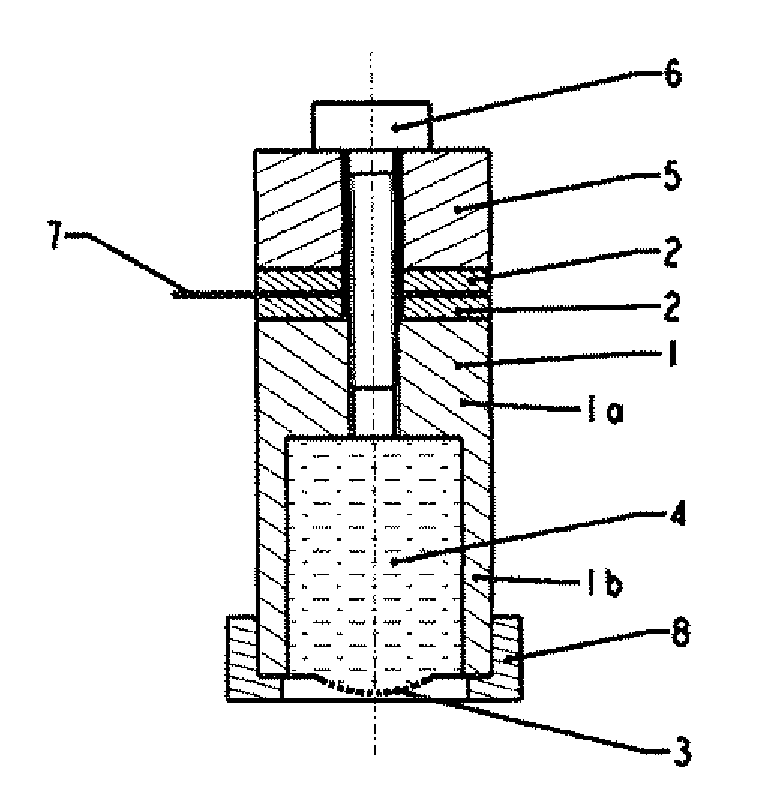
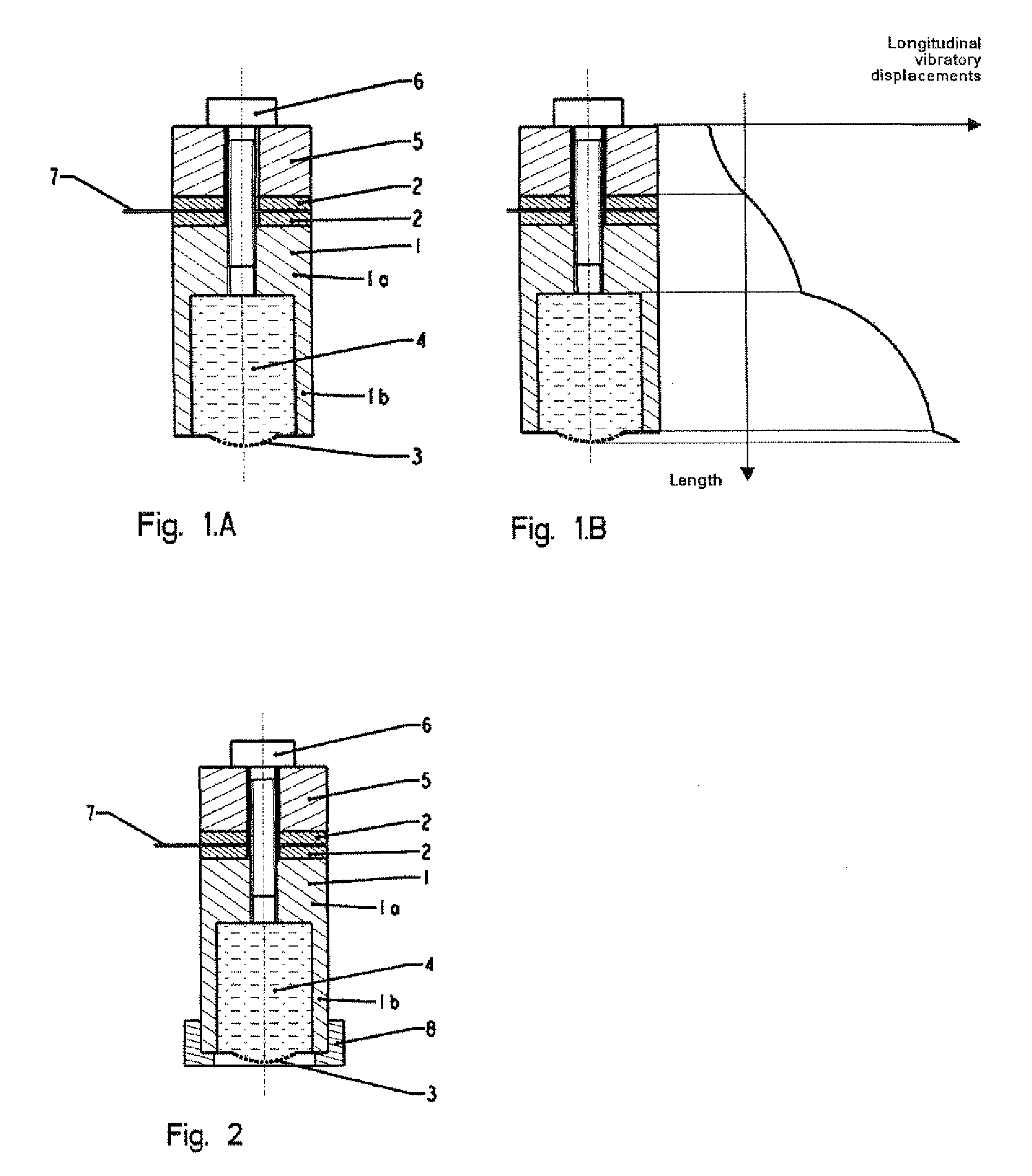
[0062]FIG. 1 is a cross-sectional representation of an exemplary atomizer according to the invention.

[0063]FIGS. 2, 3, 4, 5, 6, 7, 8, 9, 10 and 13 are cross-sectional representations of variants of this atomizer.

[0064]FIG. 11 represent the deformations of the membranes according to the structure of the atomizers.

[0065]FIG. 12 represent modelings of the vibrational behavior of the atomizer according to the present invention.

[0066]FIG. 13 is a cross-sectional representation of an atomizer including a tubular vibrating membrane placed around the “horn”, itself vibrating according to a longitudinal mode.

[0067]FIGS. 14 & 15 respectively show the perspective view and the cross sections of the cylindrical tabular or truncated cone atomizers,

[0068]FIG. 16 represents the perspective view and the cross section of ...


PUM


Abstract

The invention relates to an ultrasound liquid atomiser comprising: a rigid piezoelectric transducer body (1) having a first end defining an opening and a second end, the inside of the piezoelectric transducer body (1) comprising a cavity for containing a liquid to be atomised and said body (1) further comprising a symmetry axis; a micro-perforated membrane (3) attached on said first end and covering said opening; a piezoelectric member (2, 9) adapted and provided so as to vibrate the piezoelectric transducer body (1); characterised in that the piezoelectric member (2, 9) is located towards said second end in order to vibrate the piezoelectric transducer body (1) in a direction parallel to its symmetry axis.

Description

FIELD OF THE INVENTION [0001]The present invention relates to fluid dispensers, commonly called atomizers, that are used to accurately diffuse, by means of piezoelectric members, fluids in the form of micro-droplets or aerosols.STATE OF THE ART [0002]In many applications, fluids or liquids, whatever their nature (oily, aqueous or alcoholic), whether they are solutions or suspensions (particles suspended in a liquid), are dispensed by micronization, atomization, vaporization or aerosol generation. The main applications that use these fluid dispensing devices relate to the administration of medicines (pharmacy), the diffusion of cosmetic products (in particular perfumes), disinfection, odor generation, humidification of air or media (paper, fabrics, etc.) and the dispensing of biological reagents.[0003]Regarding medical applications, nebulizers have been employed for decades to deliver medicines by inhalation. The devices used for tins purpose can include a mechanical dosing pump, a p...

Claims


Application Information

Patent Timeline
IPC IPC(8): B05B17/06
CPCB05B17/0646A61M15/0085A61M11/005A61M2205/3379B05B17/063
Inventor SAUZADE, JEAN-DENIS
Owner TELEMAQ SAS
Why Eureka
Try Eureka