Constant current switching power supply apparatus, method of driving it, light source driving apparatus, method of driving it, and image display apparatus

a technology of constant current and power supply equipment, which is applied in the direction of electric variable regulation, process and machine control, instruments, etc., can solve the problems of long low luminance of projection television sets, and inability to drive load with stable puslative current, so as to shorten the rise time of current value and reduce the value of gain

Inactive Publication Date: 2010-02-25
MITSUBISHI ELECTRIC CORP
View PDF4 Cites 21 Cited by
  • Summary
  • Abstract
  • Description
  • Claims
  • Application Information

AI Technical Summary

Benefits of technology

[0016]said arithmetic processing circuit sets the value of the gain to a predetermined value immediately after the switching element is turned on, and reduces the value of the gain with time after the turn on of the switching element.
[0017]According to the invention, it is possible to shorten the rise time of the current, even if a relatively large pulsative current is supplied from a switching power supply.

Problems solved by technology

When the current value is relatively large, the rise time of the current value becomes long, and it is not possible to drive the load with a stable puslative current when the pulse frequency is high.
Another problem is that, when the light emitting element is driven by a pulsative current, the luminance of the projection television set is low.

Method used


Image

  • Constant current switching power supply apparatus, method of driving it, light source driving apparatus, method of driving it, and image display apparatus
  • Constant current switching power supply apparatus, method of driving it, light source driving apparatus, method of driving it, and image display apparatus
  • Constant current switching power supply apparatus, method of driving it, light source driving apparatus, method of driving it, and image display apparatus

Examples


embodiment 1

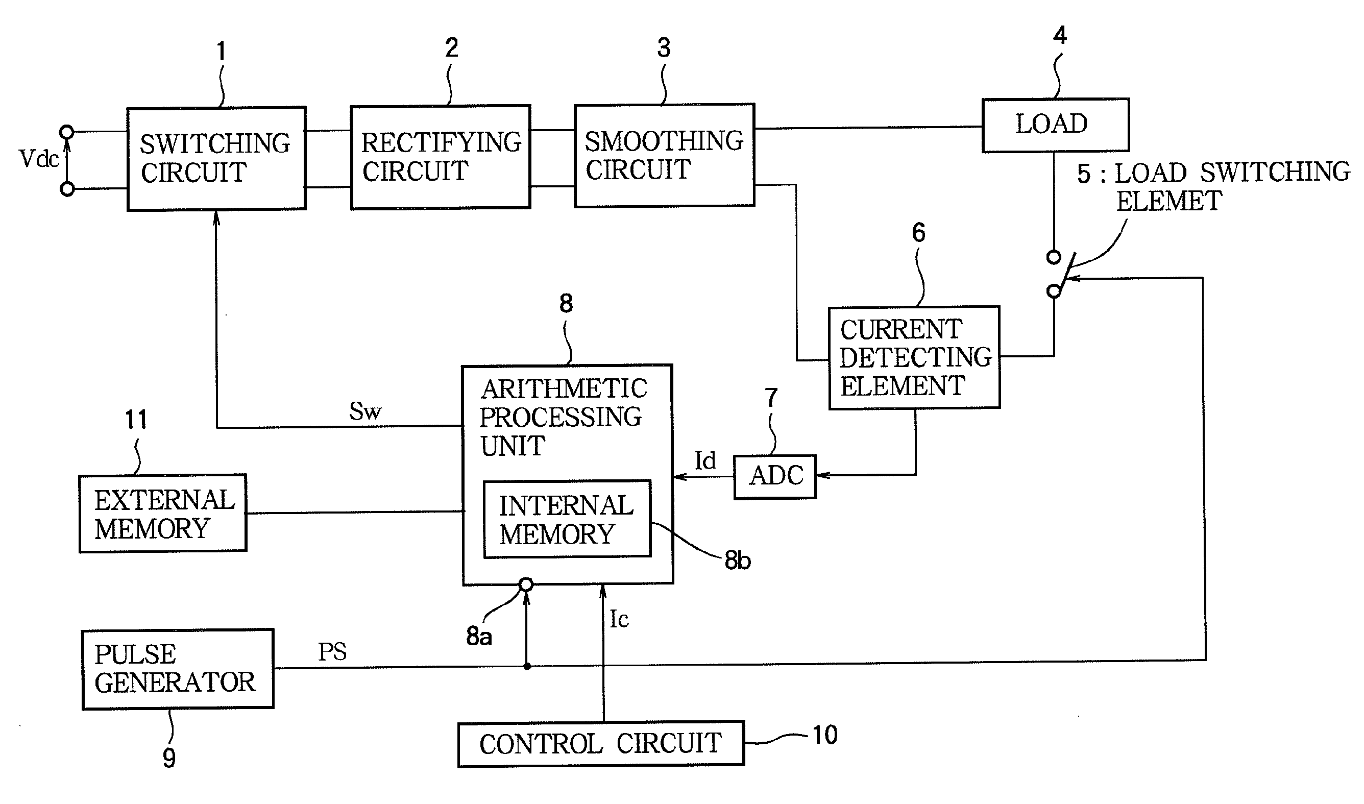
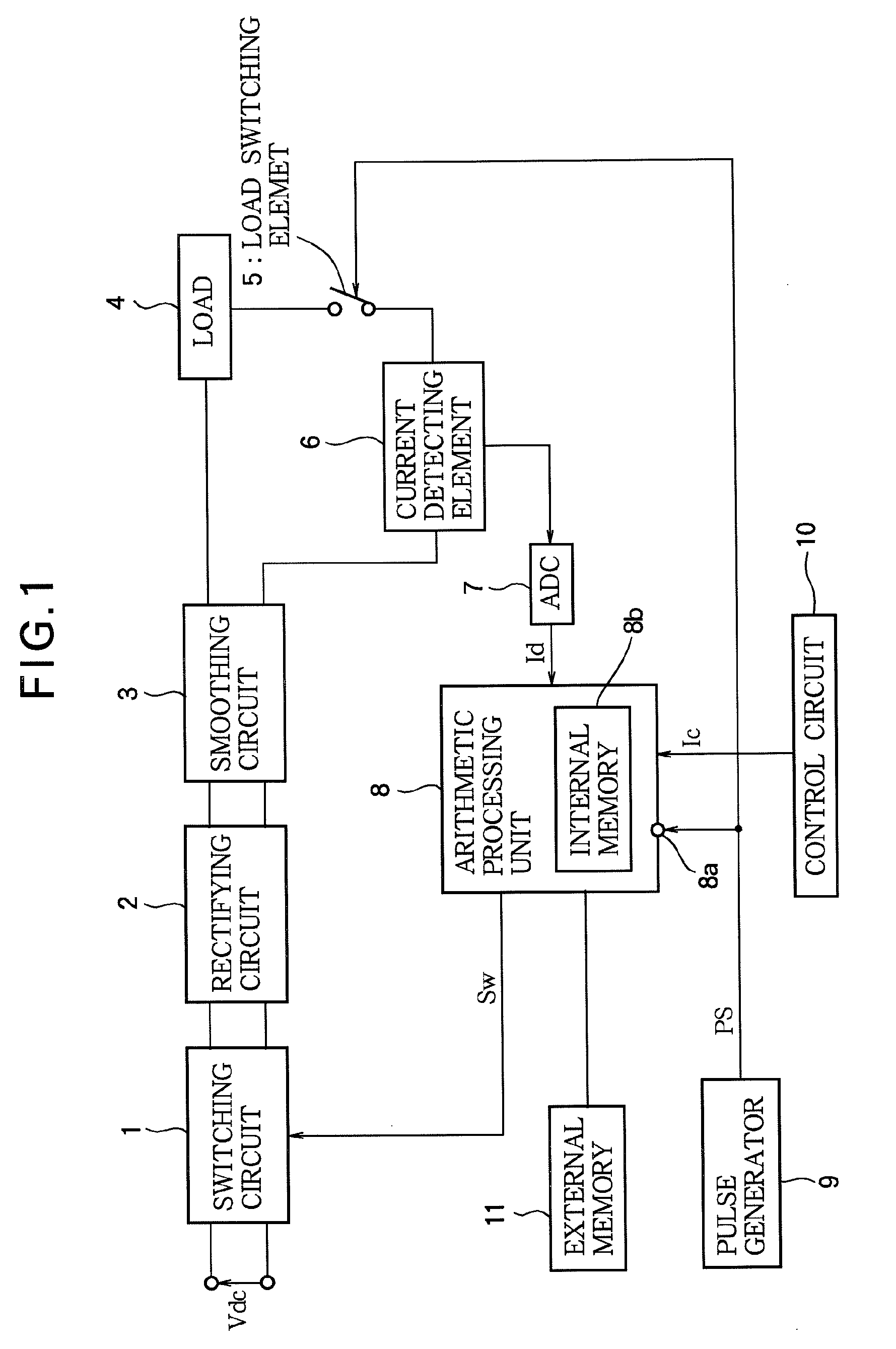
[0033]FIG. 1 is a block diagram showing a constant current switching power supply apparatus according to Embodiment 1 of the present invention. The illustrated constant current switching power supply apparatus is for controlling a current flowing through a load, and comprises a switching circuit 1, a rectifying circuit 2, a smoothing circuit 3, a load switching element 4, a current detecting element, an analog-to-digital converter (ADC) 7, and an arithmetic processing circuit B.

[0034]The invention is suitable to a situation where the load 4 is formed of a light emitting element such as an LED or an LD. The invention however is not limited to such a situation, and the load 4 may for example be a resistor.

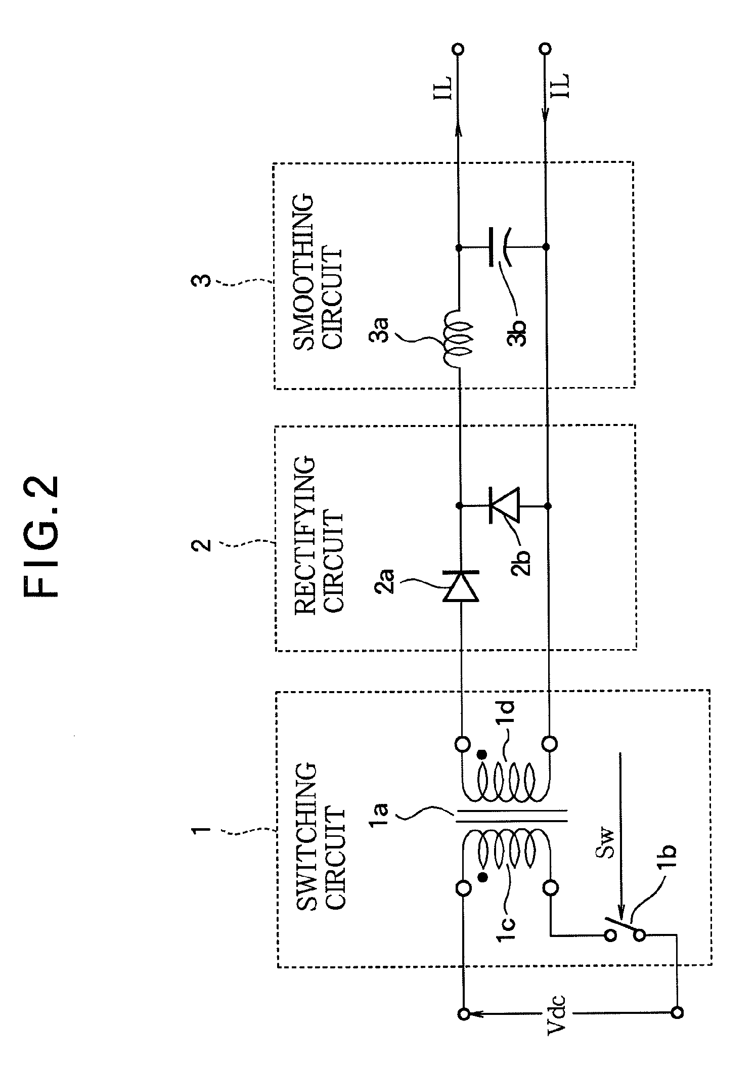
[0035]A direct current (DC) voltage is applied to the switching circuit 1. The switching circuit 1 performs switching (PWM) according to a PWM signal Sw, to generate an alternating (AC) voltage. The output voltage of the switching circuit 1 is supplied to the rectifying circuit 2. Th...

embodiment 2

[0071]FIG. 11 shows an example of an image display apparatus having a light source driving apparatus formed of a constant current switching power supply apparatus described in connection with Embodiment 1. The illustrated image display apparatus comprises a receiver 19, a video data processor 20, a timing controller 21, a spatial modulator controller 22, a spatial modulator controller 22, a light source unit 23, optical fibers 25, a light pipe 26, a lens 27, a light valve 28, a lens 29, and a screen 30. The light source unit 23 has light emitting elements 4R, 4G, and 4B, and a light source driver 24. The light emitting elements 4R, 4G, and 4B correspond to the load 4 in Embodiment 1.

[0072]Video data VD1 and a synchronous signal SY are supplied from an external image equipment, to the receiver 19. The video data VD1 is supplied from the receiver 19 to the video data processor 20. The video data VD2 processed in the video data processor 20 is input to the spatial modulator controller ...


PUM


Abstract

In a constant current switching power supply, the current flowing through the load, is feedback-controlled based on the deviation of the detection value (Id) from the target value (Ir), multiplied by a proportional gain (PG), the value of the gain is set to a predetermined value immediately after the load switching element (5) is turned on, and is thereafter gradually reduced with elapse of time. When the current to the load (4) is supplied by a PWM controlled switching circuit (1), the PWM signal is determined based on a product of the deviation and a proportional gain. It is possible to shorten the rise time of a pulsative load current in a situation where the current is relatively large.

Description

BACKGROUND OF THE INVENTION[0001]1. Field of the Invention[0002]The present invention relates to a constant current switching power supply apparatus (also called “switched-mode power supply apparatus”) which can shorten the rising time of a pulsative current, in particular a relatively large pulsative current, which is supplied from a switching power supply to a load. The invention also relates to a light source driving apparatus for driving a light source emitting light responsive to a pulsative current, and an image display apparatus displaying an image by having a light source emit light pulsatively. The invention also relates to a method driving the switching power supply apparatus, and a method of driving the light source driving apparatus.[0003]2. Description of Related Art[0004]A switching power supply apparatus is known as a small-sized power supply apparatus having a high efficiency, and is used as a power supply for electronic equipment in various devices. It is often used...

Claims


Application Information

Patent Timeline
Patent Type & Authority Applications(United States)
IPC IPC(8): H02M3/335H05B37/02
CPCH02M3/33507H05B33/086H05B33/0818H05B45/20H05B45/3725H05B45/382
Inventor YAMAMURO, TAKAHIKONAGASE, AKIHIROOKAZAKI, KOUJI
Owner MITSUBISHI ELECTRIC CORP
Why Eureka
Try Eureka