Method and apparatus for measuring fluid properties, including ph

Inactive Publication Date: 2010-02-25
KONINKLIJKE PHILIPS ELECTRONICS NV
View PDF9 Cites 11 Cited by
  • Summary
  • Abstract
  • Description
  • Claims
  • Application Information

AI Technical Summary

Benefits of technology

[0024]The present disclosure relates to a system and method for measuring fluid properties, particularly pH, within the gastrointestinal (GI) tract of a human or other fluid system, e.g., a tap water system. In an exemplary embodiment, a pH sensing method involves providing a sensing coil having an ion-selective polymer coating, the sensing coil being immersible in the fluid of a gastrointestinal tract (or other fluid system); providing a signal generator in communication with the sensing coil for applying an electrical current pulse

Problems solved by technology

Efforts at miniaturizing pH-sensing technology based on glass electrodes have had limited success.
Although an ISFET pH-sensor can be made very small, its biocompatibility has been a c

Method used


Image

  • Method and apparatus for measuring fluid properties, including ph
  • Method and apparatus for measuring fluid properties, including ph
  • Method and apparatus for measuring fluid properties, including ph

Examples


second embodiment

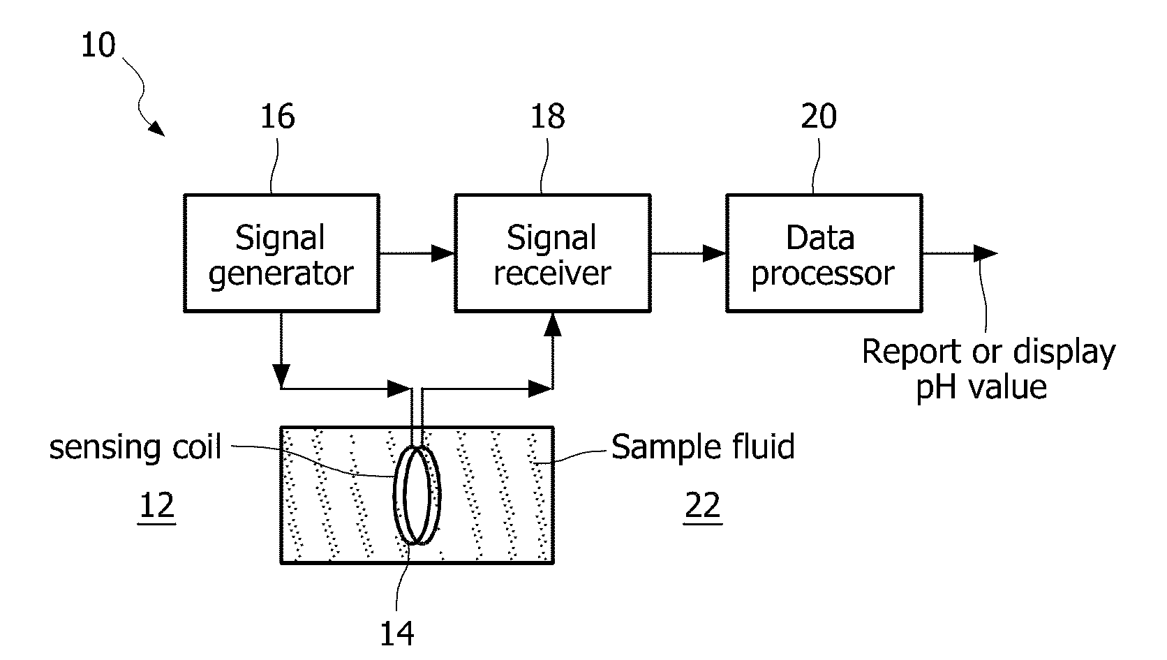
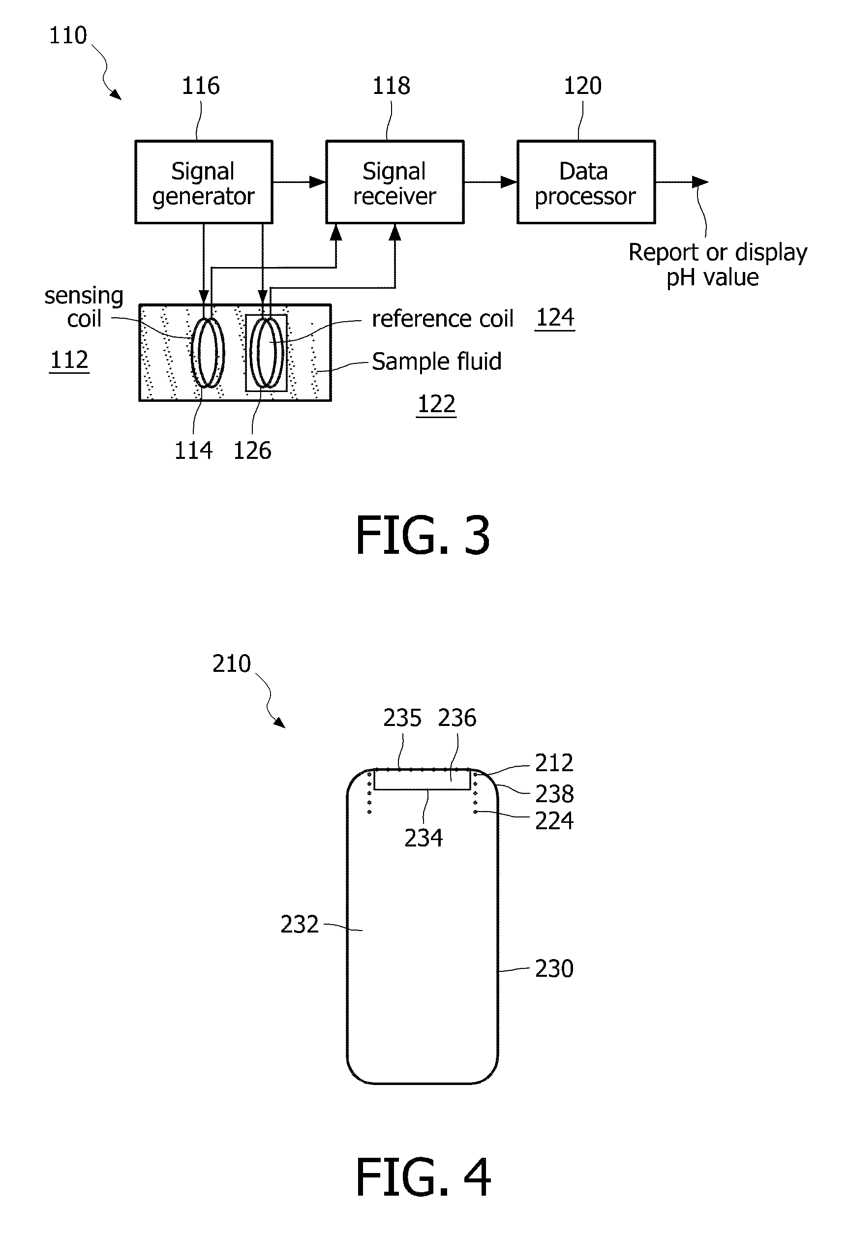
[0040]With reference to FIG. 3, a block diagram of an exemplary pH sensor having a sensing coil and a reference coil in accordance with the present disclosure is depicted. Elements illustrated in FIG. 3 which correspond to the elements described above in connection with the fluid sensor 10 of FIG. 1, have been identified by corresponding reference numbers increased by one hundred.

[0041]In the exemplary embodiment of FIG. 3, the pH sensor 110 includes a sensing coil 112 with air core 114 and a reference coil 124 with air core 126 in communication with a signal generator 116, a signal receiver 118 and a data processor 120. In the embodiment of FIG. 3, a pair of identical coils 112,124 are used to build the sensor 110. The sensing coil 112 is used to sense the sample fluid 122. The reference coil 124 is used as reference to eliminate environmental electromagnetic interference and is not exposed to the sample fluid 122. The reference coil 124 has a fixed core made of either air, liquid,...

third embodiment

[0044]With reference to FIG. 4, a block diagram of a further exemplary pH sensor 210 having a sensing coil 212 and a reference coil 224 integrated into an electronic pill shell 230 in accordance with the present disclosure is depicted. Elements illustrated in FIG. 4 which correspond to the elements described above in connection with the pH sensor 110 of FIG. 3 have been identified by corresponding reference numbers increased by one hundred. Unless otherwise indicated, both the pH sensor 110 and the pH sensor 210 have the same construction and operation. The pill shell 230 has a pill shell body 232 having a rectangular indentation 234 which is enclosed on one side by a membrane 235 so as to form a void 236 within the pill shell 232 at one end 238 of the pill shell body 232. The sensing coil 212 and the reference coil 224 are integrated into an electronic pill shell, as shown, with the sensing coil 212 employing the void 236 as its core and the reference coil 224 contained within the ...


PUM


Abstract

A fluid sensor for use within the gastro-intestinal tract of a human being is disclosed. The sensor includes a sensing coil which is immersible in the sample fluid of the gastro-intestinal tract; a signal generator in electrical with the sensing coil for applying an electrical current pulse to the sensing coil; a signal receiver in communication with the sensing coil for measuring an electrical reflection relative to said electrical current pulse; and a data processor for receiving the electrical reflection and for calculating data representative of at least one property, such as pH of the sample fluid based on the electrical reflection. The fluid sensor can also include a reference coil for calibrating the sensing coil. The sensor coil and reference coil can be encapsulated in a swallowable pill shell. The sensor coil can also function as an antenna for transmitting and receiving signals to/form a remote location.

Description

TECHNICAL FIELD [0001]The present disclosure relates to measuring fluid properties inductively and, more particularly, to a method and apparatus for measuring pH in the gastro-intestinal track (GI) of a human being or other fluid system.BACKGROUND OF THE INVENTION [0002]A coil can be modeled based on frequency-dependent impedance having a capacitive and inductive component, e.g., as shown with reference to FIG. 2. The inductance L of the coil 12 can be calculated from:L=μ0μrN2Al[0003]where,[0004]μ0 is the permeability of free space (4π'10−7 Henries per meter),[0005]μr is the relative permeability of the core 14 (dimensionless),[0006]N is the number of turns of the coil 12,[0007]A is the cross sectional area of the coil 12 in square meters,[0008]I is the length of the coil 12 in meters,Of note, the inductance L of a coil 12 is proportional to the relative permeability of the core 14.[0009]In practice, every coil also has DC resistance R and combined, distributed capacitances C. The c...

Claims


Application Information

Patent Timeline
IPC IPC(8): G01R27/26
CPCA61B5/053A61B5/42A61B5/14539A61B5/073A61B5/07A61B5/14
Inventor ZOU, HANALBU, LUCIAN REMUSSHIMIZU, JEFFDIJKSMAN, JOHAN FREDERIKPIERIK, ANKERENSEN, JUDITH MARGREETSCHLEICHER, ADAMDE JONGH, FRITS TOBI
Owner KONINKLIJKE PHILIPS ELECTRONICS NV
Why Eureka
Try Eureka