

Delay demodulation devices
- Summary
- Abstract
- Description
- Claims
- Application Information
AI Technical Summary
Benefits of technology
Problems solved by technology
Method used
Image

Examples
embodiments
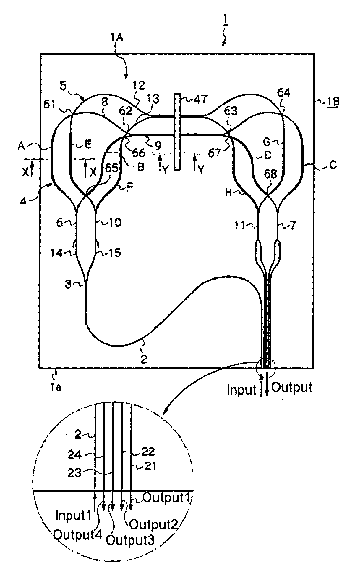
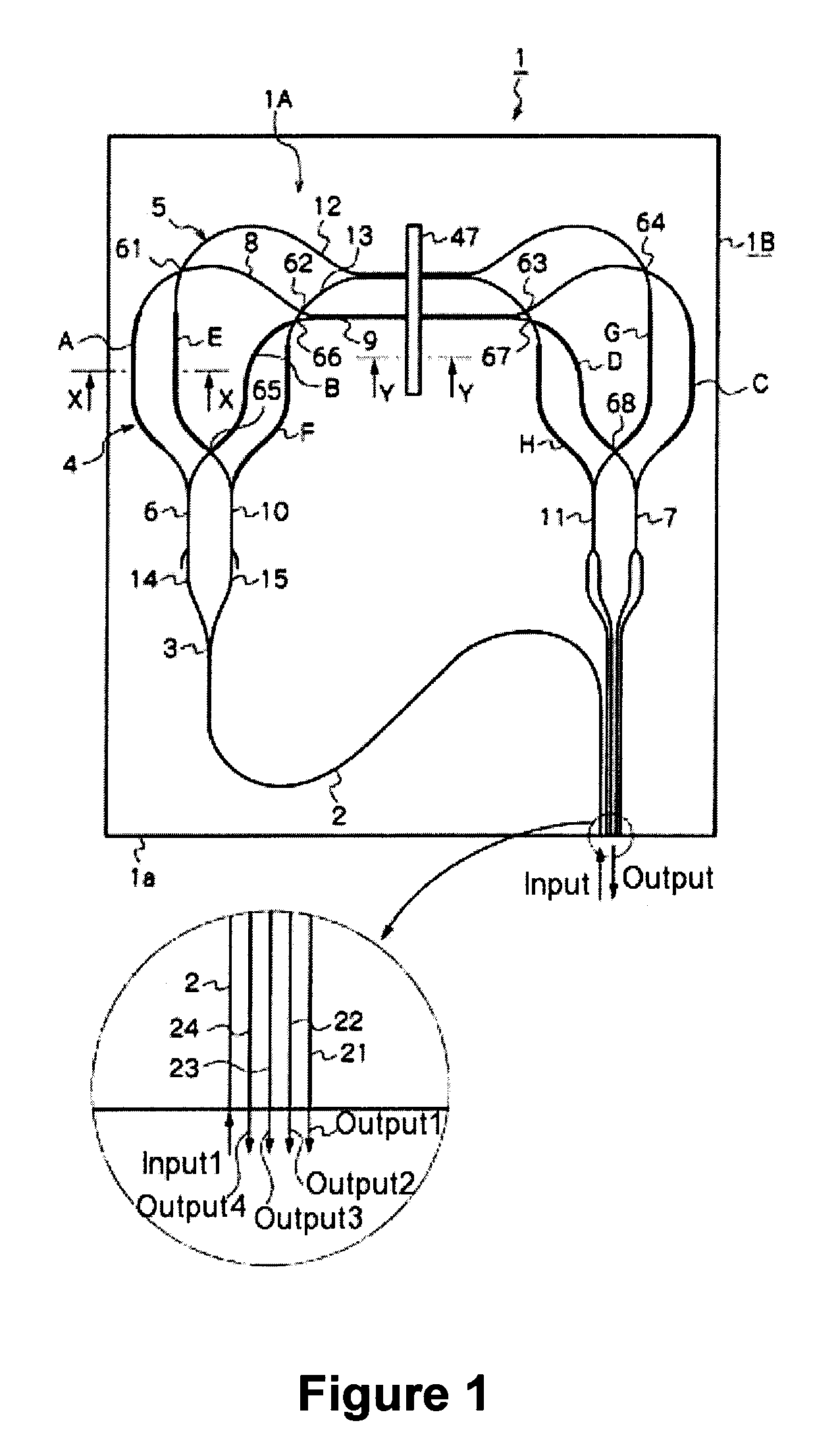
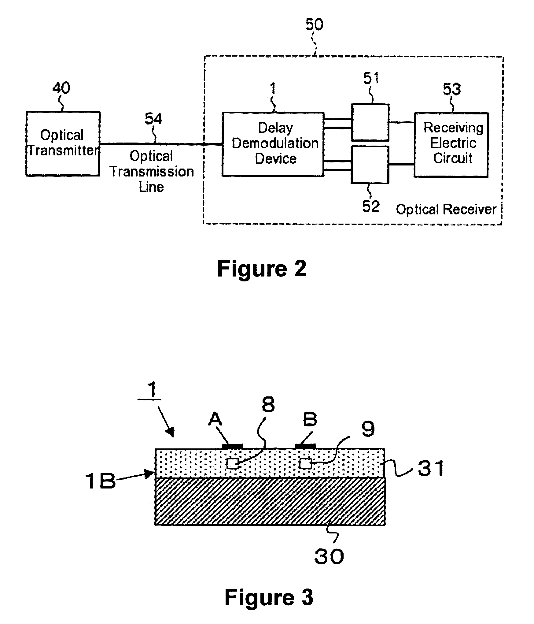
[0056]Delay demodulation device 1 has a PLC 1A on a silica base plate 30 shown in FIG. 3. The PLC 1A comprises: an input waveguide 2; a Y-shape waveguide 3; Mach-Zehnder interferometers 4, 5; and output waveguides 21˜24, wherein all of the components are made from silica glass. To create the demodulation device 1 FHD method, photo lithography, and reactive ion etching are used.
[0057]In the manufactured delay demodulation device 1, the difference in the refractive indexes between the cladding layer and the core layer (specific refractive index difference Δ) is 1.5%, and the size of the circuit (i.e. PLC chip 1B) is relatively small (i.e. 19 mm by 16 mm). Its free spectral range (FSR) is 20 GHz. The PDf is adjusted by using heaters on one of the two Mach-Zehnder interferometers 4, 5. After the adjustment, phase shift control (or phase shift trimming) is performed by using heaters on one of the two Mach-Zehnder interferometers 4, 5 to shift the phases of one Mach-Zehnder interferometer...
PUM
 Abstract
Description
Claims
Application Information