

Iron/Iron Oxide Nanoparticle and Use Thereof
a technology of iron oxide and nanoparticles, applied in the field of iron/iron oxide nanoparticles, can solve the problems that conventional nanoparticles cannot meet these requirements
- Summary
- Abstract
- Description
- Claims
- Application Information
AI Technical Summary
Benefits of technology
Problems solved by technology
Method used
Image

Examples
example 1
Materials and Methods
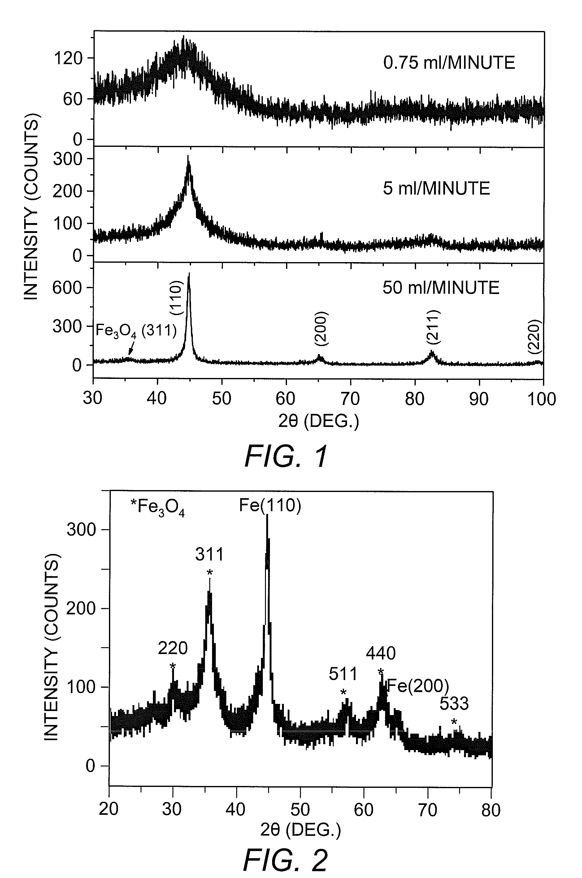
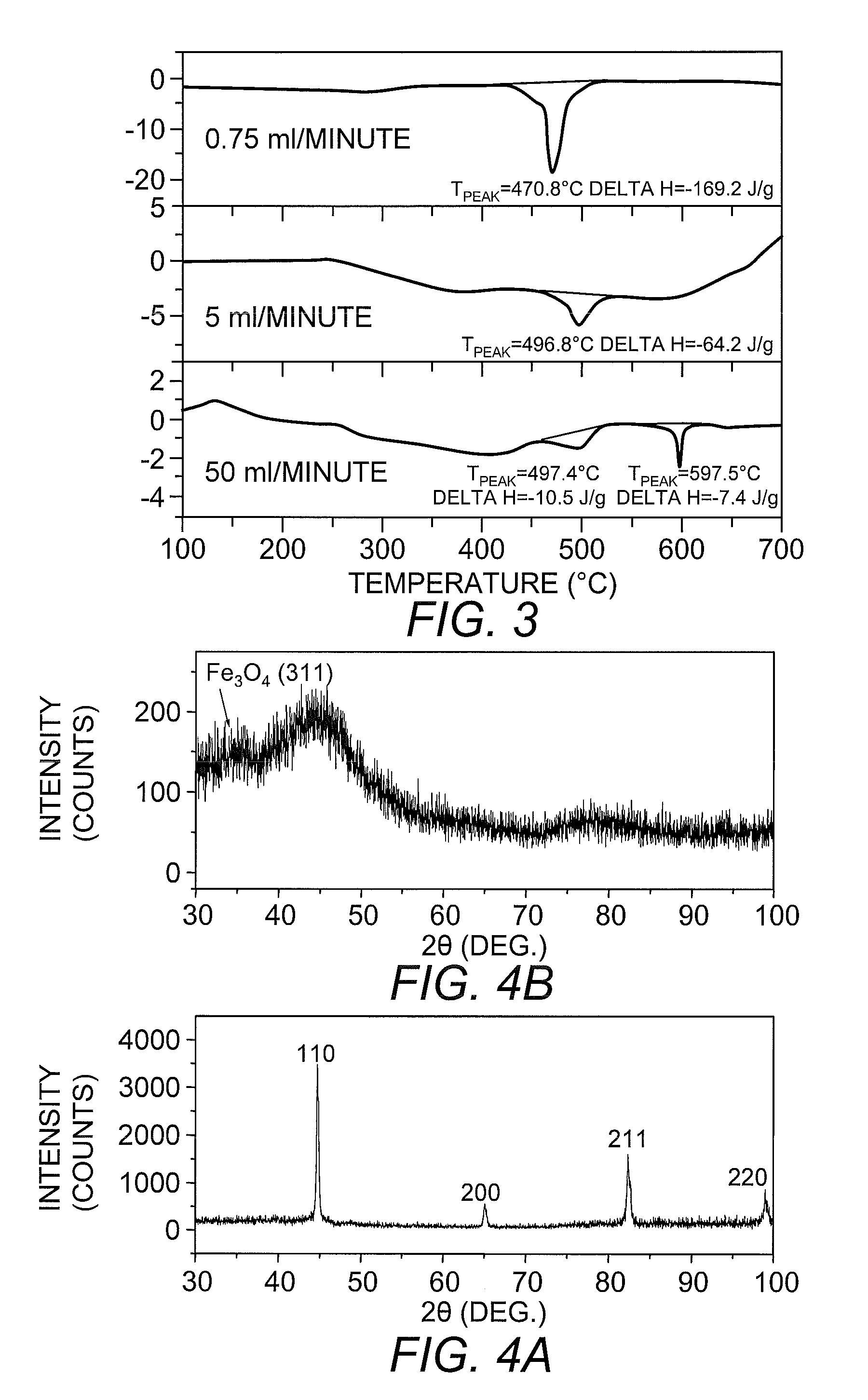
[0039]Fe2O3 nanoparticles were purchased from Alfa Aesar. Fe / Fe oxide nanoparticles were synthesized by reduction of aqueous solutions of FeCl3 within a NaBH4 solution, with or without the presence of a micro-emulsion. For synthesis of Fe / Fe oxide nanoparticle without a micro-emulsion, a typical procedure (carried out in an inert atmosphere or in aerobic conditions, at room temperature and ambient pressure) was started with dropwise addition of NaBH4 into a vigorously stirred FeCl3 solution. At the beginning of the reaction, the solution turned to a blackish color due to the precipitation of particles. The precipitates were washed with de-ionized (DI) water and acetone. Prior to use, DI water and acetone were purged with Ar for several hours to get rid of the oxygen. Anhydrous FeCl3 purchased from Alpha Aesar was stored in glove box until used. Aqueous solutions of FeCl3 were prepared immediately before nanoparticle synthesis using prepurged DI water.
[0040]After...
example 2
Characterization of Nanoparticles
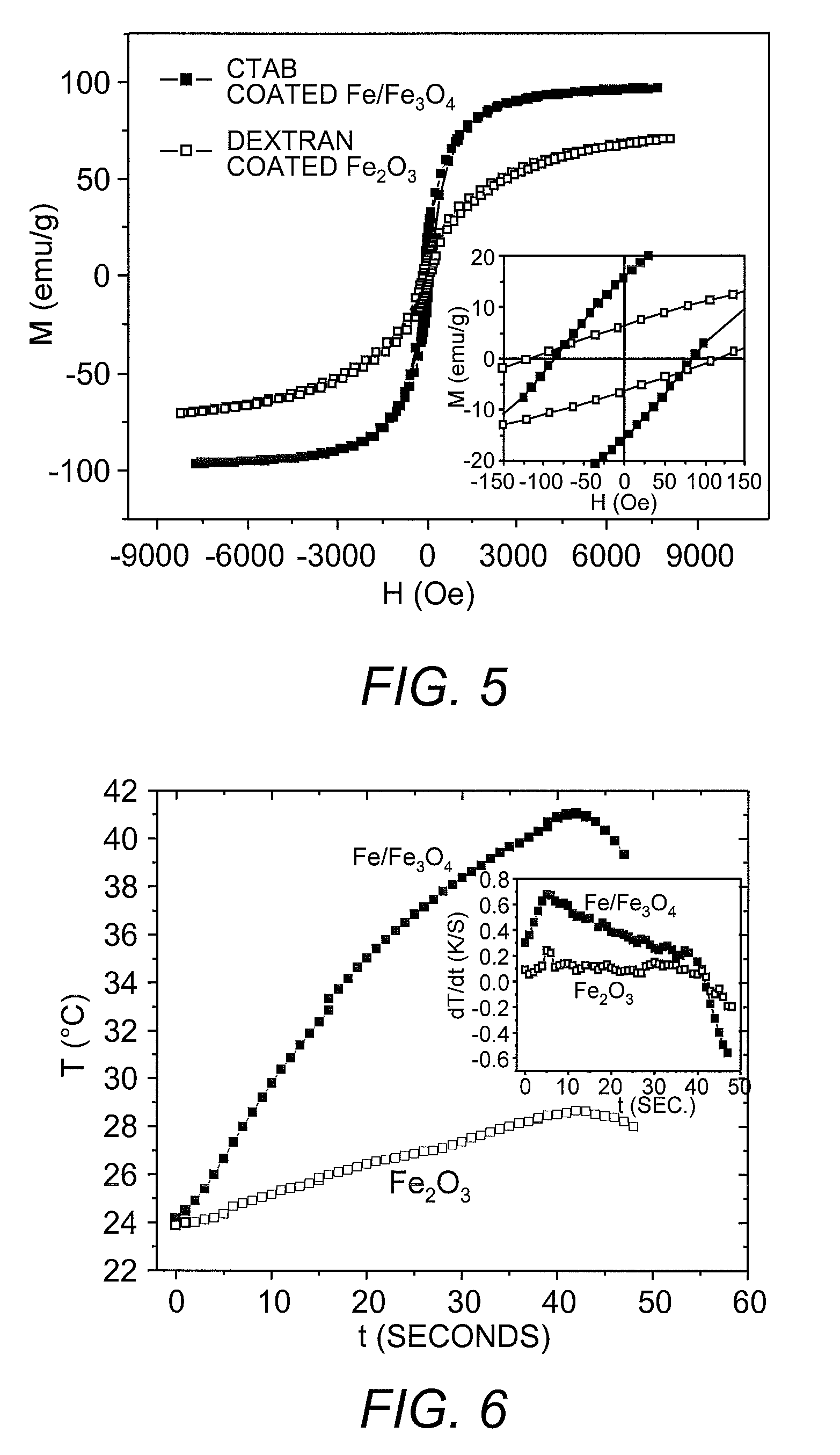
[0048]To achieve the development of sufficient heat at the lowest possible frequency and the smallest external magnetic field strength, iron / iron oxide nanoparticles were produced. The iron / iron oxide combination was selected because iron has a high MS (>210 emu / g), while the MS of iron oxides are ≦90 emu / gram. Theoretically, the hysteresis power loss to heat is given by the frequency times the integral of B·dH over a closed loop, where B is the inductive magnetization. As such, Fe nanoparticles can have high enough coercivities for hyperthermia with limited applied field amplitudes, and since B for iron is more than twice that of iron oxides, the power losses of a single domain Fe particle can be more than twice that of an iron oxide particle.
[0049]While ferromagnetic particles such as Fe can be imaged with MRI, the contrast is much less than the contrast that can be achieved with SPIO nanoparticles. Accordingly, the instant nanoparticles combine a ...
example 3
[0063]It is important to be able to image the nanoparticle distribution to identify the locations that should be treated and differentiate them from the locations where nanoparticles collect normally, such as the liver. The most commonly employed contrast mechanism is the fact that nanoparticles increase the transverse relaxation rate of the adjacent water in gradient echo images, which creates darker regions in the image at their location. To test the imaging characteristics of the instant nanoparticles, vials of the CTAB-coated Fe / Fe3O4 particles and Dextran-coated Fe oxide and particles with different concentrations were imaged in a 3 T Philips Achieva MRI using a pair of 4 inch local pickup coils to achieve the highest signal-to-noise possible. Three-dimensional gradient echo images were obtained with constant TR and variable TE values to calculate the R2* decay constant for each concentration and type of nanoparticles. The 256 by 102 pixel images had i...
PUM
| Property | Measurement | Unit |
|---|---|---|
| Composition | aaaaa | aaaaa |
| Magnetic field | aaaaa | aaaaa |
| Metallic bond | aaaaa | aaaaa |
Abstract
Description
Claims
Application Information