
Pouch-typed secondary battery with improved safety and excellent manufacturing process property

a manufacturing process and secondary battery technology, applied in the direction of cell components, final product manufacturing, sustainable manufacturing/processing, etc., can solve the problems of battery catching fire or explosion, thermal runaway phenomenon, etc., and achieve the effect of improving safety, stably maintaining and more stably fixing

Active Publication Date: 2010-02-25
LG ENERGY SOLUTION LTD
View PDF6 Cites 57 Cited by
  • Summary
  • Abstract
  • Description
  • Claims
  • Application Information

AI Technical Summary

Benefits of technology

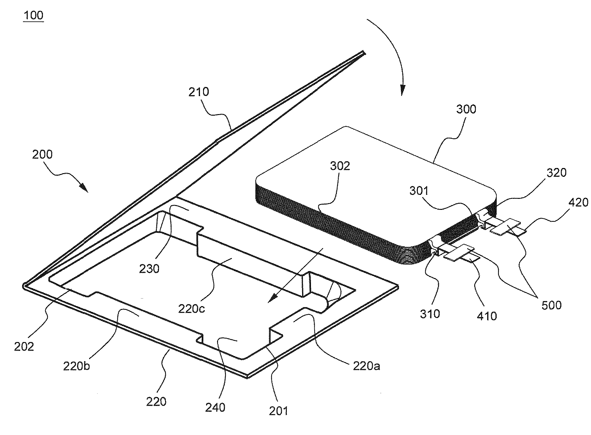
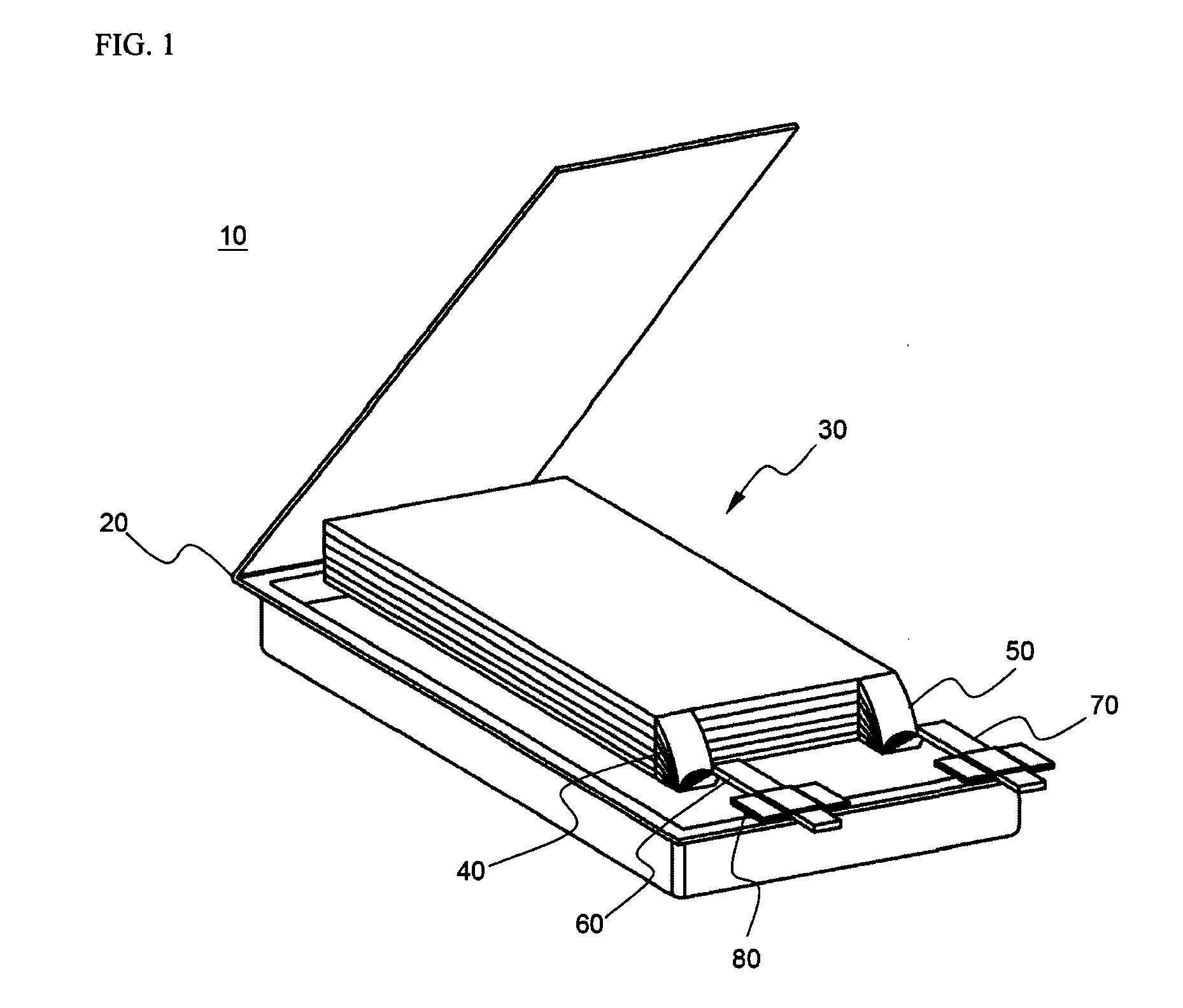
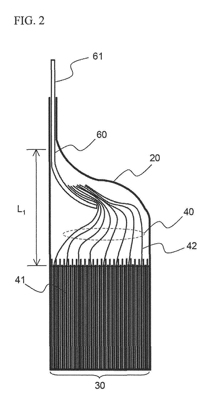
[0017]As a result of a variety of extensive and intensive studies and experiments to solve the problems as described above, the inventors of the present invention have found that, when a receiving part of a battery case, corresponding to electrode tab-electrode lead coupling portions (V-form regions) and opposite sides of an electrode assembly, mounted in a secondary battery, is deformed into a predetermined shape, such that the electrode assembly is brought into tight contact with corresponding regions of the battery case, the movement of the electrode assembly due to external impact to the secondary battery, such as dropping of the secondary battery, is restrained, thereby preventing the occurrence of a short circuit in the secondary battery, and the deformation of the receiving part of the battery case and the installation of the electrode assembly in the receiving part of the battery case are easily accomplished. The present invention has been completed based on these findings.
[0038]More preferably, the thermal welding is also performed to the step regions when the battery case is sealed by the thermal welding. Since the battery case, made of the laminate sheet, has low mechanical strength, the battery case may be easily deformed when an external force is applied to the battery case. As a result, the step regions may be deformed when large pressure is applied to the step regions from the electrode assembly due to various causes. When the step regions of the battery case are thermally welded, on the other hand, such deformation of the step regions is fundamentally prevented, and therefore, the desired safety of the secondary battery is secured.

Problems solved by technology

The internal short circuit of a battery due to the dropping of the battery or the application of external impact to the battery may act as a principal cause of explosion or combustion of the battery.
When the interior temperature of the battery exceeds a critical temperature level due to the resistance heat, the oxide structure of a cathode active material collapses, and therefore, a thermal runaway phenomenon occurs.
As a result, the battery may catch fire or explode.

Method used


Image

  • Pouch-typed secondary battery with improved safety and excellent manufacturing process property
  • Pouch-typed secondary battery with improved safety and excellent manufacturing process property
  • Pouch-typed secondary battery with improved safety and excellent manufacturing process property

Examples


example 1

[0058]A cathode mixture slurry was prepared by adding 95 weight percent of lithium cobalt oxide as a cathode active material, 2.5 weight percent of a conducting agent, and 2.5 weight percent of a binder to N-methyl-2-pyrrolidone (NMP) as a solvent. An anode mixture slurry was prepared by adding 95 weight percent of artificial graphite as an anode active material, 1.5 weight percent of a conducting agent, and 3.5 weight percent of a binder to NMP as a solvent. The cathode mixture slurry was coated on an aluminum foil, and was then dried and pressed to manufacture cathodes. The anode mixture slurry was coated on a copper foil, and was then dried and pressed to manufacture anodes.

[0059]The cathodes and the anodes were stacked while separators were disposed between the cathodes and the anodes to manufacture cathode bicells and anode bicells. Subsequently, the bicells were sequentially stacked, while the bicells were arranged on a long separation film, to manufacture a stacking-folding t...

experimental example 1

[0061]Dropping experiments were carried out on the batteries manufactured according to Example 1 and Comparative example 1. The experiment results are indicated in Table 1 below. The dropping experiments were repeatedly carried out using 32 batteries for each example. In the dropping experiments, the batteries were freely dropped from a height of 1.5 m such that the upper end of each battery, at which the electrode tab-electrode lead coupling portions are formed, collided with the ground.

TABLE 1Number of batteries short-circuited after droppingExample 10Comparative example 18

[0062]As can be seen from Table 1 above, the experiment results revealed that all the batteries manufactured according to Example 1 were not short-circuited after the dropping experiments. Specifically, the electrode assembly was stably fixed by the concave steps formed at each battery case, with the result that the movement of the electrode assembly was restrained, in spite of the impact applied to each battery...

experimental example 2

[0063]Forcible moving experiments were carried out on the electrode assembly mounted in the respective battery cases manufactured according to Example 1 and Comparative example 1. The positional relations between the electrode assemblies and the corresponding battery cases before and after the experiments are illustrated in FIGS. 7 and 8. The distance between the electrode assemblies and the corresponding battery cases, before and after external impacts were applied to the batteries, is approximately indicated in the photographs.

[0064]Referring to FIGS. 7 and 8, the experiment results revealed that the side-to-side movement and the vertical movement of the electrode assembly was greatly reduced for the battery manufactured according to Example 1 as compared to the battery manufactured according to Comparative example 1. Specifically, when an impact was applied to the battery manufactured according to Comparative example 1, the distance between the electrode assembly and the battery ...


PUM


Abstract

Disclosed herein is a secondary battery including an electrode assembly, having pluralities of electrode tabs joined to electrode leads, mounted in a receiving part of a battery case, wherein the battery case has concave steps formed at the inner upper end of the receiving part thereof between electrode tab-electrode lead coupling portions (a cathode terminal portion and an anode terminal portion) of the electrode assembly and at the inner opposite sides of the receiving part thereof corresponding to the opposite sides of the electrode assembly such that the electrode assembly is in tight contact with the concave steps.

Description

FIELD OF THE INVENTION[0001]The present invention relates to a secondary battery with improved safety and excellent manufacturing processability, and, more particularly, to a secondary battery including an electrode assembly, having pluralities of electrode tabs joined to electrode leads, mounted in a receiving part of a battery case, wherein the battery case has concave steps formed at the inner upper end of the receiving part thereof between electrode tab-electrode lead coupling portions (a cathode terminal portion and an anode terminal portion) of the electrode assembly and at the inner opposite sides of the receiving part thereof corresponding to the opposite sides of the electrode assembly such that the electrode assembly is in tight contact with the concave steps.BACKGROUND OF THE INVENTION[0002]As mobile devices have been increasingly developed, and the demand for such mobile devices has increased, the demand for batteries has also sharply increased as an energy source for th...

Claims


Application Information

Patent Timeline
IPC IPC(8): H01M2/04H01M50/105H01M50/124H01M50/178H01M50/528H01M50/54H01M50/55H01M50/553H01M50/566
CPCH01M2/021H01M2/0217H01M2/0277H01M2/0285H01M2/0287H01M2/22H01M2/266H01M10/0436H01M10/052H01M10/0525H01M10/0565H01M10/0585Y02E60/122H01M2/06H01M2/0207H01M2/0275Y02P70/50Y02E60/10H01M50/124H01M50/528H01M50/54H01M50/105H01M50/178H01M50/55H01M50/553H01M50/566H01M10/0583H01M50/121H01M50/119H01M50/131H01M2300/0082H01M50/103
Inventor LEE, WOOYONGCHOI, BYUNGJINLEE, HYANG MOKAHN, CHANG BUMJANG, JUN HWAN
Owner LG ENERGY SOLUTION LTD
Learn More