Method of making lightweight structures

a lightweight structure and manufacturing method technology, applied in the field of making lightweight structures, can solve the problems lack of suitable production process, and many manual activities which are very time-consuming, and achieve the effect of affecting fuel consumption

Inactive Publication Date: 2010-03-04
BENTELER SGL
View PDF12 Cites 31 Cited by
  • Summary
  • Abstract
  • Description
  • Claims
  • Application Information

AI Technical Summary

Benefits of technology

[0014]After calendering the stack of prepregs and coating their surface, the respective stack is cut to size to the desired geometry. This can be done for example by a stamping device or a cutter. As different lightweight structures can be produced, each blank can be cut to a different geometry. Of course, when a large-scale production is involved, series of same blanks, i.e. same geometry, should be produced first. As a result of the advantageous surface coating of the prepreg, tool contamination is eliminated. The finished blanks are stacked in a special charge carrier.
[0015]The production of lightweight structures or fiber-reinforced structures may be realized by directly pressing the blanks into the base elements to be reinforced. It is, of course, also conceivable, to apply an adhesive onto the blanks so as to realize a combination of pressing and bonding instead of direct pressing-in. In addition to both these process variants, the base element to be reinforced can be placed in a heating station before being deposited in the press tool. An example of a heat source includes an IR radiation field which is placed upstream of the press tool. When being placed in the heat station, the base element to be reinforced is heated, preferably within few seconds, to curing temperature of the resin and then transferred to the press tool which is heated conventionally. In this way, a time-intensive heating of the base structure to be reinforced with accompanying slower curing or pre-curing of the prepreg is avoided.
[0019]In principle, the stacks of prepregs or prepreg layers are calendered onto one another under load considerations in a number needed for the reinforcements. The uppermost and lowermost layer may hereby be formed by non-stick films or by a non-stick film on top and a non-woven layer on the bottom. The presence of non-stick films facilitate transport and prevent tool contamination used in the process. The non-woven layer serves the same purpose but in addition may also serve as carrier or spacer for the adhesive layer because the non-woven layer becomes impregnated with resin during pressing so that the layer next to the non-woven should be made rich in resin. The stack of prepregs may be formed in a press tool and cured in accordance with a process variant, whereby appropriate selection of the resin system and curing temperature enables realization of curing or pre-curing sufficient for consolidation within e.g. five minutes.
[0020]According to another process variant, the base elements to be reinforced are heated to the curing or pre-curing temperature of the matrix resin by a heat source so as to avoid prolonged heating times in the tool.
[0028]As an alternative to step five, adhesive may be applied onto the blanks (step 6) before the blanks are placed in the base element to be reinforced. Suitable application of adhesive avoids contamination of the produced structure or tools (press tool) as a result of the compressed material. Of course, the base elements to be reinforced are exposed to a heat source and heated to curing temperature analogous to step five.
[0034]The addition of 0.1-50% of the modifier component to the base prepreg resin or matrix resin, preferably 2-10%, currently preferred 4-9%, results in a significant increase of the matrix toughness while attaining a comparably great stiffness, strength, and heat resistance of the fiber-plastic composite portion. The modification leads to a significantly enhanced adhesion of the fiber-plastic composite onto the steel sheet so that the application of an adhesive layer and the associated process step can be eliminated.

Problems solved by technology

Any single component of motor vehicles adds weight and thus adversely affects fuel consumption.
Still, there is a lack of a suitable production process that allows a large-scale production of such fiber-reinforced structures at suitable clock time.
The reason for that is the need for numerous manual activities which are very time-consuming.
Also, curing of matrix resins used during production of these components is time-consuming.

Method used


Image

  • Method of making lightweight structures
  • Method of making lightweight structures
  • Method of making lightweight structures

Examples


Embodiment Construction

[0042]Throughout all the figures, same or corresponding elements may generally be indicated by same reference numerals. These depicted embodiments are to be understood as illustrative of the invention and not as limiting in any way. It should also be understood that the figures are not necessarily to scale and that the embodiments are sometimes illustrated by graphic symbols, phantom lines, diagrammatic representations and fragmentary views. In certain instances, details which are not necessary for an understanding of the present invention or which render other details difficult to perceive may have been omitted.

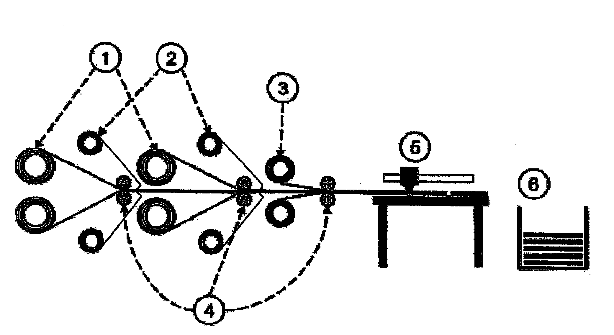
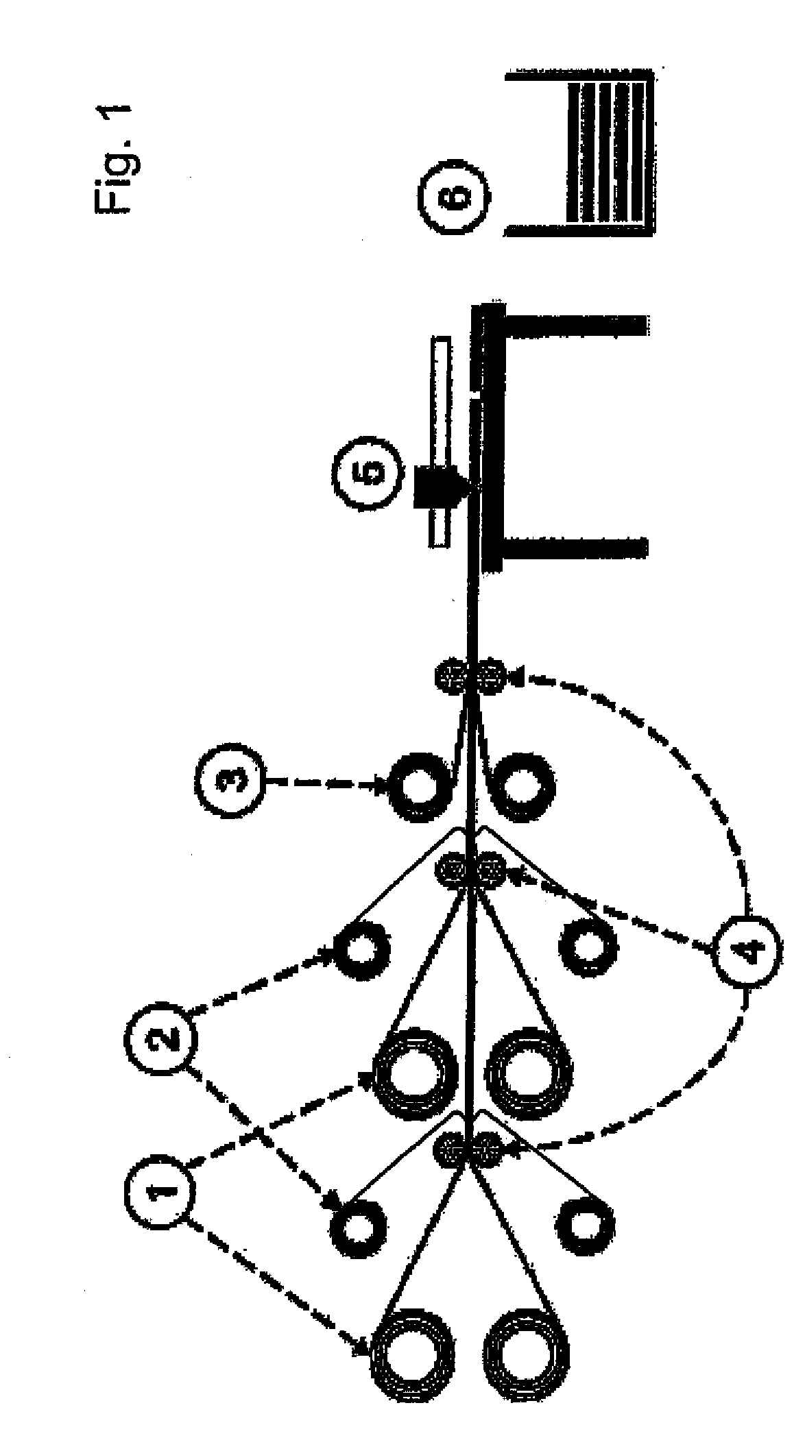
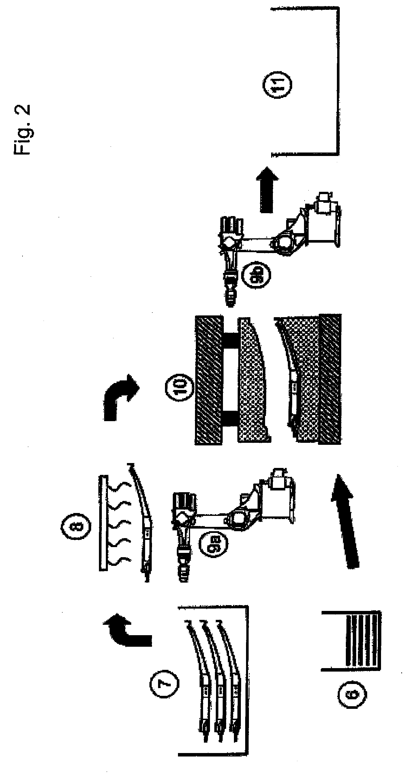
[0043]Turning now to the drawing, and in particular to FIG. 5, there is shown in general a sequence diagram of method steps S1 to S8 of a method for making lightweight structures or fiber-reinforced structures in accordance with the present invention. Steps S5 to S7 are hereby to be understood as an alternative embodiment.

[0044]Step S1: A stack of prepregs is built-up succes...


PUM

PropertyMeasurementUnit
timeaaaaaaaaaa
timeaaaaaaaaaa
temperaturesaaaaaaaaaa

Abstract

In a method of making a lightweight structure composed of a reinforced base element and a reinforcement element, the reinforcement element is fabricated, and the base element is heated by a heat source to a curing or pre-curing temperature. Subsequently the heated base element is joined together with the reinforcement element in a press tool.

Description

CROSS-REFERENCES TO RELATED APPLICATIONS[0001]This application claims the priority of German Patent Application, Serial No. 10 2008 039 869.1, filed Aug. 27, 2008, pursuant to 35 U.S.C. 119(a)-(d), the content of which is incorporated herein by reference in its entirety as if fully set forth herein.BACKGROUND OF THE INVENTION[0002]The present invention relates to a method of making lightweight structures or fiber-reinforced structures.[0003]The following discussion of related art is provided to assist the reader in understanding the advantages of the invention, and is not to be construed as an admission that this related art is prior art to this invention.[0004]Any single component of motor vehicles adds weight and thus adversely affects fuel consumption. Thus, the automobile industry tries to design the respective components as lightweight as possible while still complying with the demands on component properties such as, e.g., strength, stiffness and service life.[0005]Against the...

Claims


Application Information

Patent Timeline
Patent Type & Authority Applications(United States)
IPC IPC(8): C09J5/06B32B38/04B29C65/02
CPCB29C35/02Y10T156/1062B29C43/14B29C65/44B29C65/52B29C66/721B29C66/742B29C70/46B29C70/504B29C2035/0822B29K2105/06B29K2105/0854B29K2305/12B29L2031/3002B29C65/524B29K2705/00B29C66/5326B29C65/4835B29C65/4865B29C43/003B29C66/8322B29C66/7394B29C66/71B29C70/86B29C66/1122B29K2063/00
Inventor BOKE, JOHANNESMACIEJ, MARKOGOJNY, FLORIAN H.HOWE, CHRISTIANGRASSER, SEBASTIANWOHLETZ, BERNDHEILMEIER, GERHARD
Owner BENTELER SGL
Why Eureka
Try Eureka