
Space heater with electrostatically assisted heat transfer and method of assisting heat transfer in heating devices

a technology of space heater and electrostatic assisted heat transfer, which is applied in the direction of fluid heater, air heater, light and heating apparatus, etc., can solve the problems of fan space heater, failure to provide air cleaning or disinfection, prior art devices that do not incorporate additional entertainment features such as music, sound effects, soothing sounds, etc., to maximize the time that ozonated air travels and minimizes the area

Inactive Publication Date: 2010-03-04
KRICHTAFOVITCH IGOR A +1
View PDF17 Cites 22 Cited by
  • Summary
  • Abstract
  • Description
  • Claims
  • Application Information

AI Technical Summary

Benefits of technology

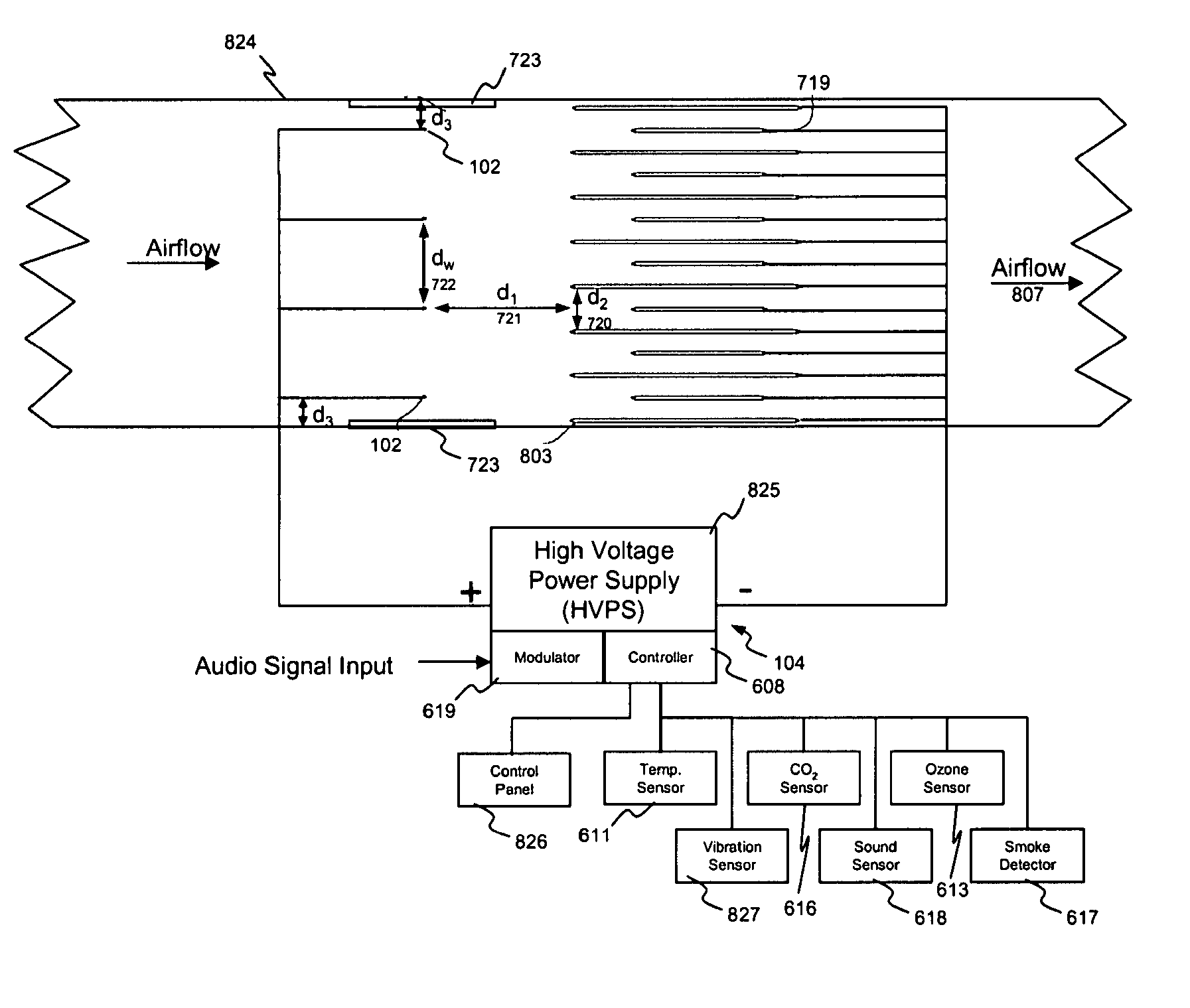
[0011]Thus, the present invention is directed to an apparatus and method for enhancing the efficiency of a space heater, incorporating an ionic gas propulsion mechanism, such as a corona discharge device, to transport ambient air through a heat exchanger. The heat exchanger is configured to warm the ambient air using both heat energy produced by a heat source such as electrical heating, burning action (e.g., combustion), chemical reaction, hot by-product utilization or otherwise. Embodiments of the invention further include air scrubber functions for collecting particulates present in the air including biohazardous pollution. Further embodiments include audio modulation of the air to produce sound, such as music or simulated natural noise, and / or cancel or attenuate undesirable sounds and noises.
[0060]According to another feature of the invention the space heater has a minimized area though which ozonated air may escape heated zones heated by the heating component and maximize time that ozonated air travels trough these hot zones.

Problems solved by technology

For example, another deficiency of fan space heaters according to the prior art is the failure to provide air cleaning or disinfection.
Still another deficiency is the failure of prior art devices to incorporate additional entertainment features such as music, sound effects, or soothing sounds and / or reduce unpleasant and / or unwanted sound such as produced by the burning wood or outside wind whistling in the chimney.

Method used


Image

  • Space heater with electrostatically assisted heat transfer and method of assisting heat transfer in heating devices
  • Space heater with electrostatically assisted heat transfer and method of assisting heat transfer in heating devices
  • Space heater with electrostatically assisted heat transfer and method of assisting heat transfer in heating devices

Examples


Embodiment Construction

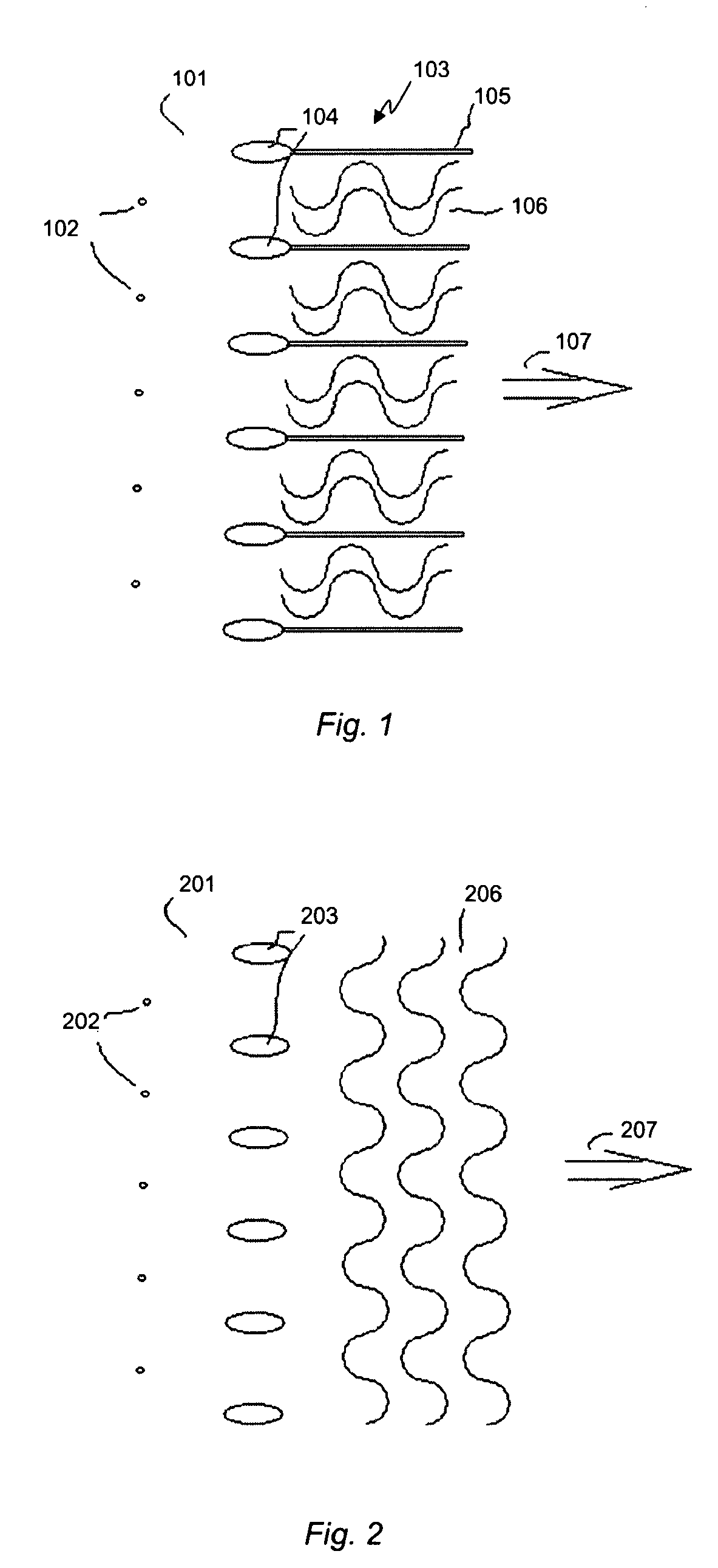
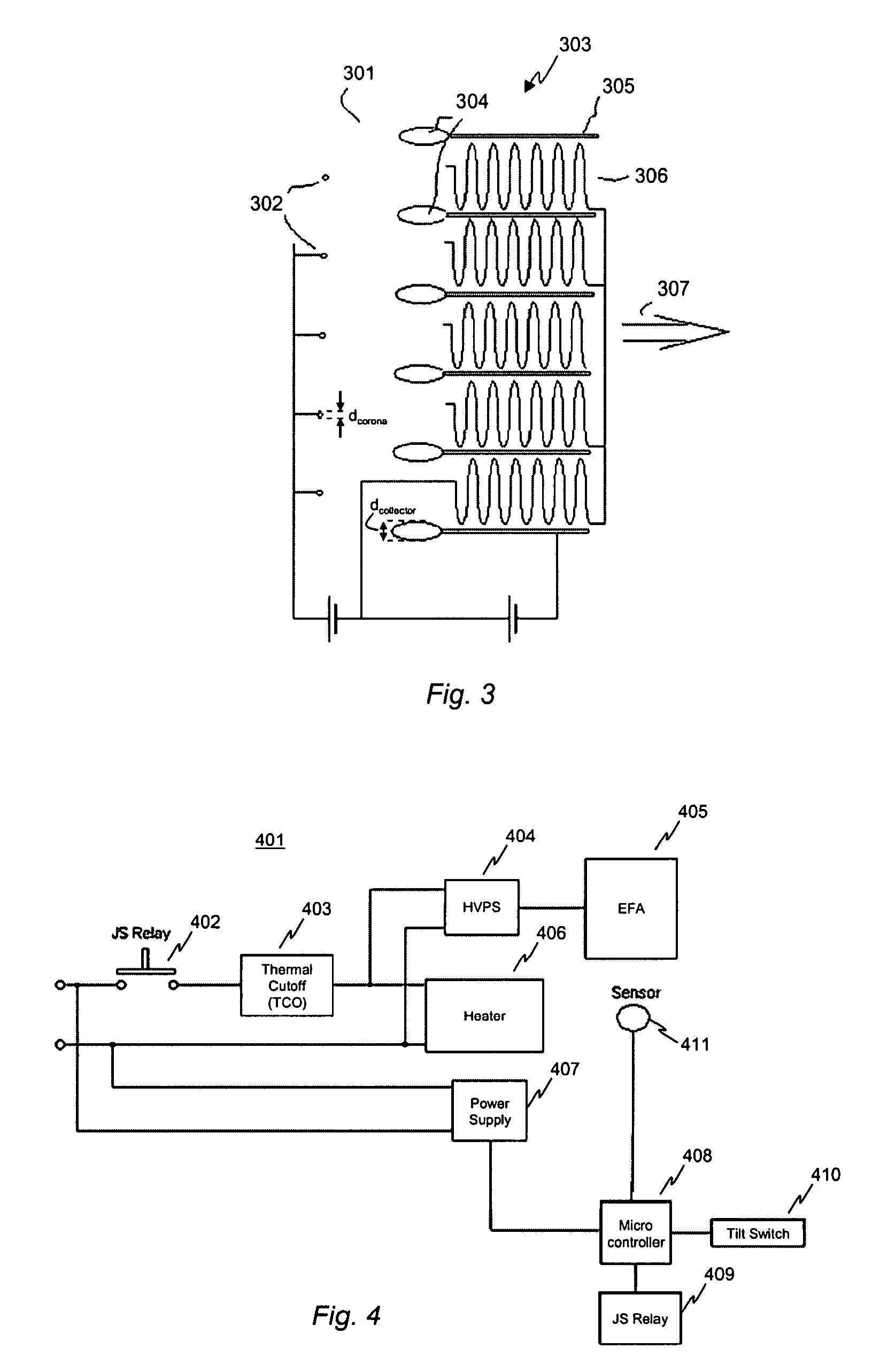
[0069]In the FIG. 1 the space heater 101 is shown schematically. Space heater 101 includes of the corona wire-like electrodes 102 (shown in cross section), collecting electrodes 103 each including a leading edge of front portion 104 and trailing or tail portions 105. Filament components 106 are located between the tail portions 105 of collecting electrodes 103.

[0070]The HVPS (not shown) supplies a high voltage potential difference between the corona wires 102 and the collecting electrodes 103. As a result of the corona discharge an airflow is induced in the direction shown by the arrow 107. It is important that the filament 106 is located in such a manner as to occupy all the area between collecting electrodes 103 to prevent ozonated air to escape hot zone, i.e. where the filament is located.

[0071]In the FIG. 2 space heater 201 is shown schematically including corona wire-like electrodes 202 (shown in cross section), the collecting electrodes 203, and the filament components 206 loc...


PUM


Abstract

A space heater for heating air includes a duct for transporting air from an inlet to an outlet of the duct; a heating component; and an electrostatic discharge device within the duct for accelerating the gas through the duct from the inlet to the outlet. The electrostatic discharge device may include a high voltage power supply; at least one corona electrode connected to the high voltage power supply; and a collector electrode located proximate the corona electrode and connected to the high voltage power supply so as to induce a motion of the gas in a direction from the corona electrode toward the collector electrode.

Description

CROSS-REFERENCE TO RELATED APPLICATIONS[0001]This application claims the priority of U.S. Provisional Patent Application Ser. No. 60 / 863,946, filed Nov. 1, 2006, entitled “Space Heater with Electrostatically Assisted Heat Transfer and Method ff Assisting Heat Transfer in Heating Devices”, the entire disclosure of which is specifically incorporated herein in its entirety by reference.BACKGROUND OF THE INVENTION[0002]1. Field of the Invention[0003]The invention relates to heat distribution and, in particular, a heating apparatus including an electrical corona discharge device to enhance heat distribution and provide associated functionalities and corresponding method.[0004]2. Description of the Related Art[0005]Space heaters, such as electrically powered convection heaters, are designated for primary and supplemental heating of dwellings, offices, and other spaces. The heated air provided by the space heater provides the user with physical comfort. Unfortunately, a traditional space h...

Claims


Application Information

Patent Timeline
IPC IPC(8): F24H3/02
CPCB03C3/08B03C3/12B03C3/368F24H3/00B03C2201/04B03C2201/14B03C3/455
Inventor KRICHTAFOVITCH, IGOR A.GOROBETS, VLADIMIR L.
Owner KRICHTAFOVITCH IGOR A
Learn More