
Barrier coatings for interconnects; related devices, and methods of forming

a barrier coating and interconnect technology, applied in the direction of electroforming by electrophoresis, solid-state diffusion coating, electrodialysis, etc., can solve the problems of reducing the performance of the cell on continuous use, affecting the performance of the device, so as to prevent the formation of strontium chromate

Active Publication Date: 2010-03-04
CUMMINS ENTERPRISE LLC
View PDF8 Cites 62 Cited by
  • Summary
  • Abstract
  • Description
  • Claims
  • Application Information

AI Technical Summary

Benefits of technology

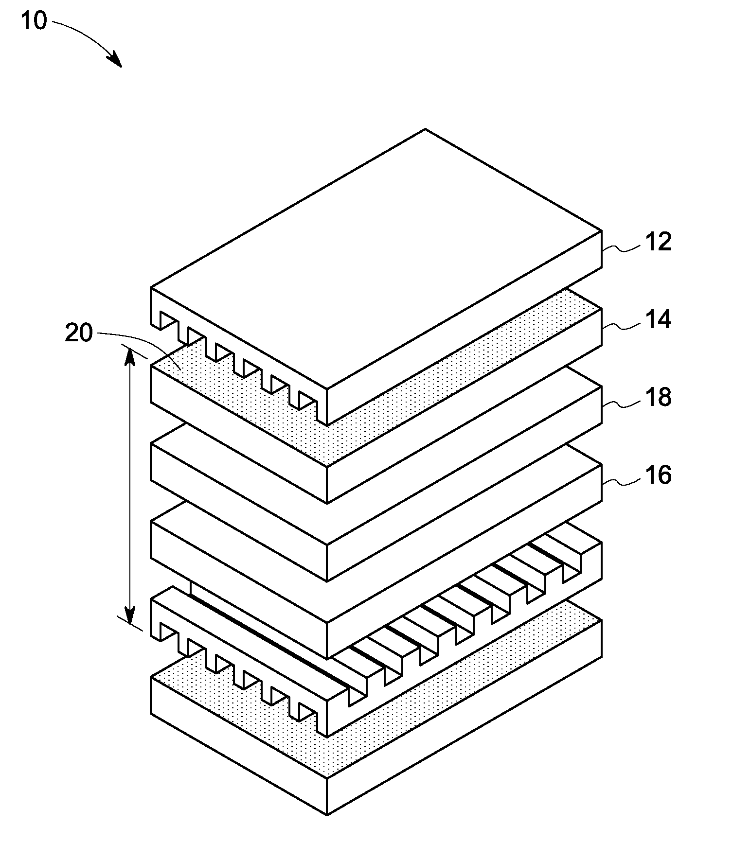
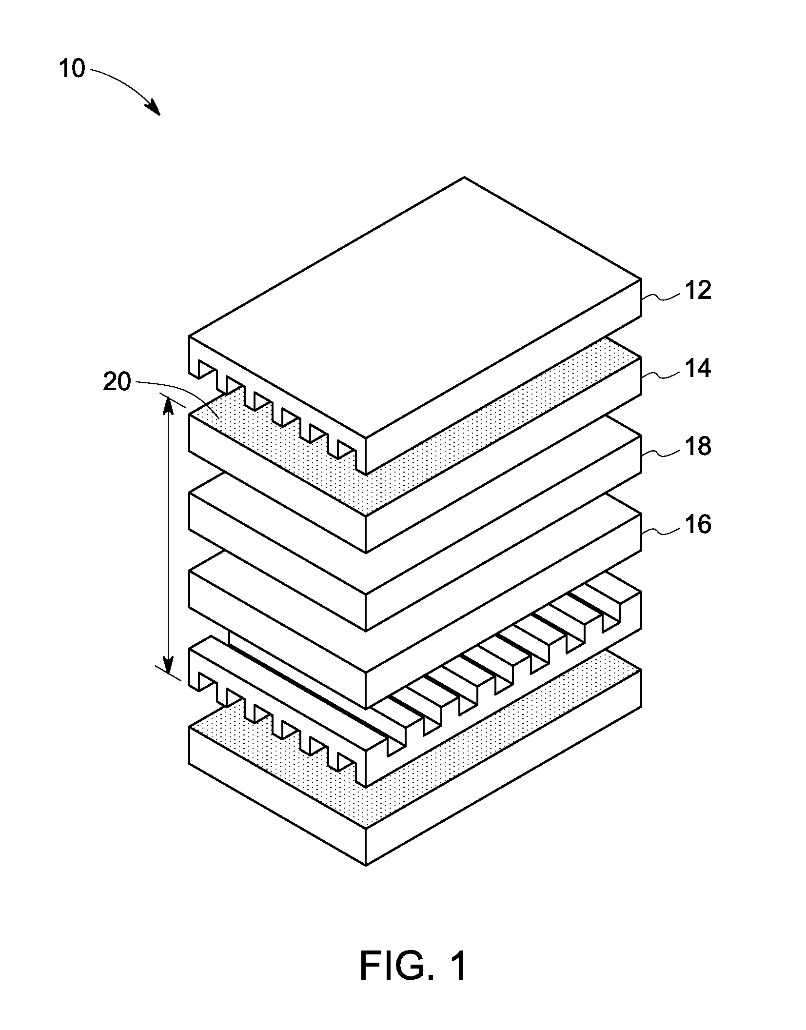
The present invention provides a barrier coating between a cathode layer and an interconnect that prevents the formation of strontium chromate. This results in a more reliable and durable solid oxide fuel cell. The method of preparing the fuel cell involves forming a cathode layer comprising a strontium composition on a ceramic electrolyte layer, and then adding a barrier layer between the cathode layer and an overlying interconnect structure comprising chromium. This barrier layer prevents the formation of strontium chromate and improves the performance and reliability of the fuel cell.

Problems solved by technology

One of the most commonly observed problems in solid oxide fuel cells utilizing these materials is the decrease in the performance of the cell on continuous usage.
One of the reasons for degradation of performance is Cr-poisoning of the cathode.
This type of reaction can degrade the performance of the device.
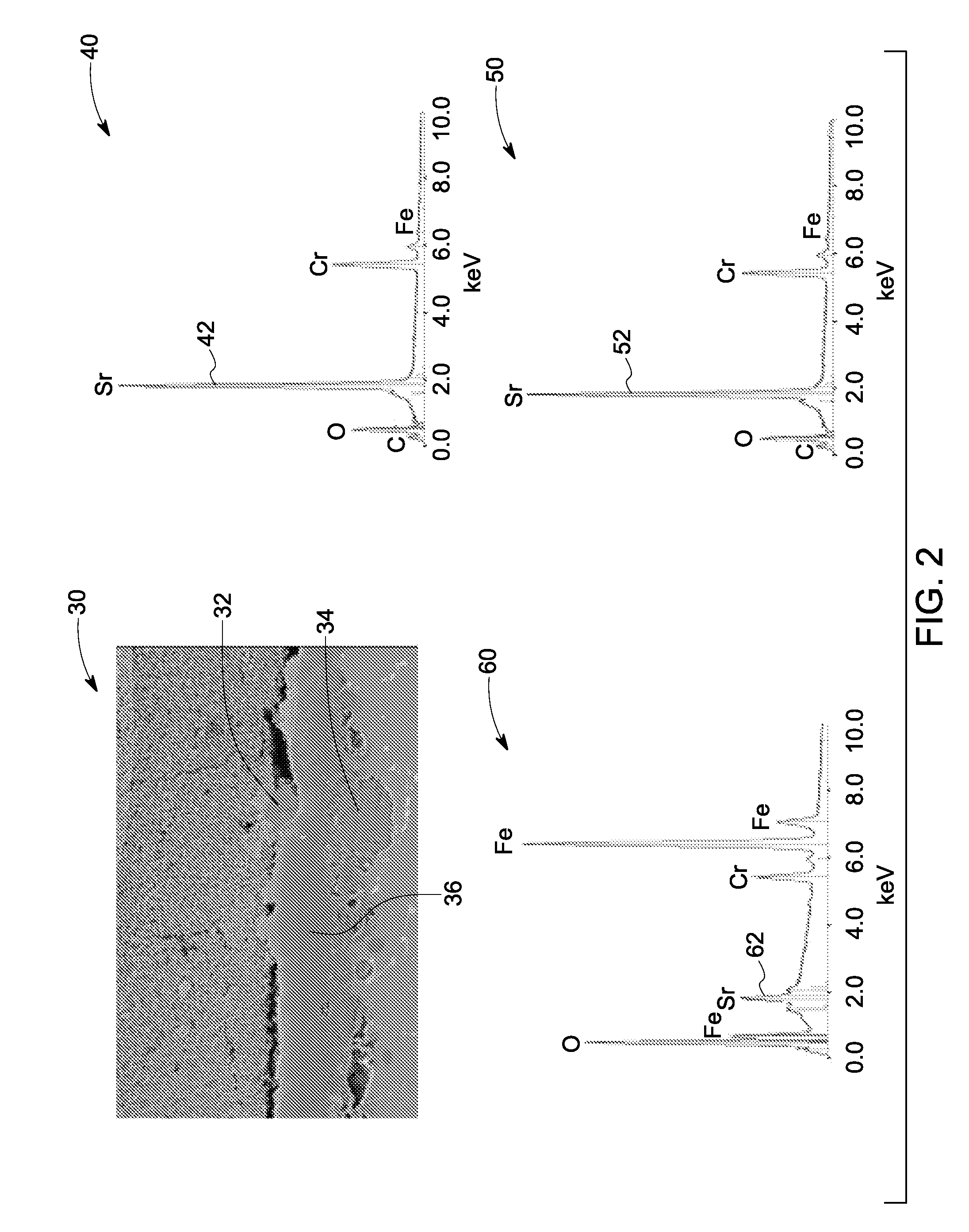
Another cause of performance degradation in solid oxide fuel cells is the formation of low conductivity strontium chromate at the interface between the interconnect and the cathode layers.
The thickness of the formed strontium chromate layer can increase during the prolonged or intermittent operation of the solid oxide fuel cell, and thereby degrade the performance of the device.

Method used


Image

  • Barrier coatings for interconnects; related devices, and methods of forming
  • Barrier coatings for interconnects; related devices, and methods of forming
  • Barrier coatings for interconnects; related devices, and methods of forming

Examples


example

[0051]The following example serves to illustrate some of the features and advantages offered by the present invention, and is not intended to limit the invention thereto.

[0052]Mn3O4 (CAS 1317-37-7, FW228.81, −325 mesh) was obtained from Aldrich Chemical Company. A stock binder solution was prepared by dilution of V006 with α-terpineol in a ratio of 1.3 grams of V006 to each gram of additional α-terpineol. Different ratios of Mn3O4, the stock solution, and acetone were milled in a paint shaker with 100 g of zirconia media for 4 hours. The acetone was added to decrease drying time, which produced a rapid increase in the viscosity of the coating. This reduced the tendency of the coating to flow after the initial coating application. Some examples of the amounts (taken in grams) are shown in Table 1.

TABLE 1Composition of Mn3O4 slurryCompositionAcetoneStock SolutionMn3O414020202402025340203044020405402060

[0053]The interconnect was cleaned twice in an ultrasonic bath with detergent (Alcon...


PUM

PropertyMeasurementUnit
thicknessaaaaaaaaaa
thicknessaaaaaaaaaa
ionic conductivityaaaaaaaaaa

Abstract

A method of preparing a solid oxide fuel cell is described herein, as well as the fuel cell itself. The method comprises forming a cathode layer comprising a strontium composition on a ceramic electrolyte layer; and forming a barrier layer between the cathode layer and an overlying interconnect structure comprising chromium, so as to substantially prevent the formation of strontium chromate.

Description

BACKGROUND OF THE INVENTION[0001]The invention is generally related to fuel cells. More particularly, the invention is related to barrier coatings for interconnects, e.g., interconnects for solid oxide fuel cells. The invention is also related to a method of forming barrier coatings for interconnects, and devices made therefrom.[0002]Chromium (Cr) containing electrical conductors such as ferritic stainless steels are widely used as interconnect (IC) materials in solid oxide fuel cells (SOFCs), because of their excellent oxidation resistance. These materials have the advantage of typically forming a thin Cr-rich oxide scale that protects the electrical conductors from rapid oxidation. The fuel cells also include a cathode; and the cathode materials often include strontium-based compositions such as lanthanum strontium ferrite, lanthanum strontium managanite, and lanthanum strontium cobalt ferrite.[0003]One of the most commonly observed problems in solid oxide fuel cells utilizing the...

Claims


Application Information

Patent Timeline
Patent Type & Authority Applications(United States)
IPC IPC(8): H01M8/10B05D5/12C23C4/08C23C8/08H05H1/24C23C14/34B32B37/02C25D13/02C25D5/00
CPCC23C18/1216C23C18/1254C23C24/082C25D13/02H01M8/021Y02E60/525H01M8/0297H01M8/1213H01M2008/1293Y02E60/521H01M8/0228Y02E60/50H01M8/0258H01M8/0267H01M8/2432
Inventor KEBBEDE, ANTENEHOFORI-OKAI, GABRIEL KWADWOKLUG, FREDERIC JOSEPHALINGER, MATTHEW JOSEPHLEWIS, DANIEL JOSEPH
Owner CUMMINS ENTERPRISE LLC
Learn More