Apparatus and method for treatment of bifurcation lesions

a bifurcation and apparatus technology, applied in multi-lumen catheters, blood vessels, surgery, etc., can solve the problems of many limitations of the use of a single tip port through which a single guide wire is threaded, the risk of side branches being occluded or lost during the procedure, and the physician is at risk of losing placement or occluding side branches during the procedure, so as to improve the degree of physician control over the procedure, improve the long-term results level a bifurcation lesions and treatment, applied in the field of bifurcation lesions and apparatus and treatment, which is applied in the field of application, the effect of bifurcation lesions and the use of single guide wires, the effect of the patient's long-term results

Active Publication Date: 2010-03-04
URETSKY BARRY F
View PDF0 Cites 67 Cited by
  • Summary
  • Abstract
  • Description
  • Claims
  • Application Information

AI Technical Summary

Benefits of technology

[0019]The use of a catheter with single tip port through which a single guide wire is threaded has many limitations in situations involving bifurcated lesions. However, the use of a novel design disclosed herein that contemplates two or more guide wire ports at the distal tip of a single catheter permits the physician to manipulate the catheter with greater accuracy and reliability when treating bifurcation lesions in vessels. The use of two or more guide wires in conjunction with a single catheter allows the physician to begin the procedure by accurately locating the proper main branch and one or more side branches without having to thereafter remove a guide wire from any of the vasculature during the remainder of the procedure. This advance allows a much higher level of physician control over the procedure and permits the physician to revisit and confirm the integrity of the procedure without ever having to remove and reinsert a guide wire. The physician is also free to trust the guide wires will remain in proper position from the outset of the procedure and continuing through the duration of the procedure. Without guide wires, the physician runs the risk of occluding side branches or losing placement during the procedure. Once the several guide wires are in place and located in the proper region, the physician can then use virtually any commercially available catheter, balloon, and wire stent apparatus to treat the region. Alternatively, the physician may elect to thread more specialized catheters having various qualities and characteristics along the already-placed guide wires. The physician can also selectively insert tailored catheters along the already-placed guide wires throughout the procedure. That is, the physician may elect to insert a wire stent of a particular diameter along a first guide wire and thereafter or simultaneously insert a typical balloon or catheter having a different sized wire stent using another guide wire already positioned in, for example, a side branch vessel. The treatment of bifurcation lesions thus becomes less about trying to find the proper branches at various times throughout the procedure. The present apparatus and related methodology allows a physician to dedicate time and attention to using the full panoply of various stenting technology in an efficient and predictable way, by starting the procedure with the present apparatus that enable the physician to use multiple guide wires that are placed in the proper locations early in the procedure using one flexible apparatus. The proposed method of placement of stent placements is intended to improve long-term results by decreasing the severity of turbulent flow associated with all previously described methods.

Problems solved by technology

The use of a catheter with single tip port through which a single guide wire is threaded has many limitations in situations involving bifurcated lesions.
Without guide wires, the physician runs the risk of occluding side branches or losing placement during the procedure.

Method used


Image

  • Apparatus and method for treatment of bifurcation lesions
  • Apparatus and method for treatment of bifurcation lesions
  • Apparatus and method for treatment of bifurcation lesions

Examples


Embodiment Construction

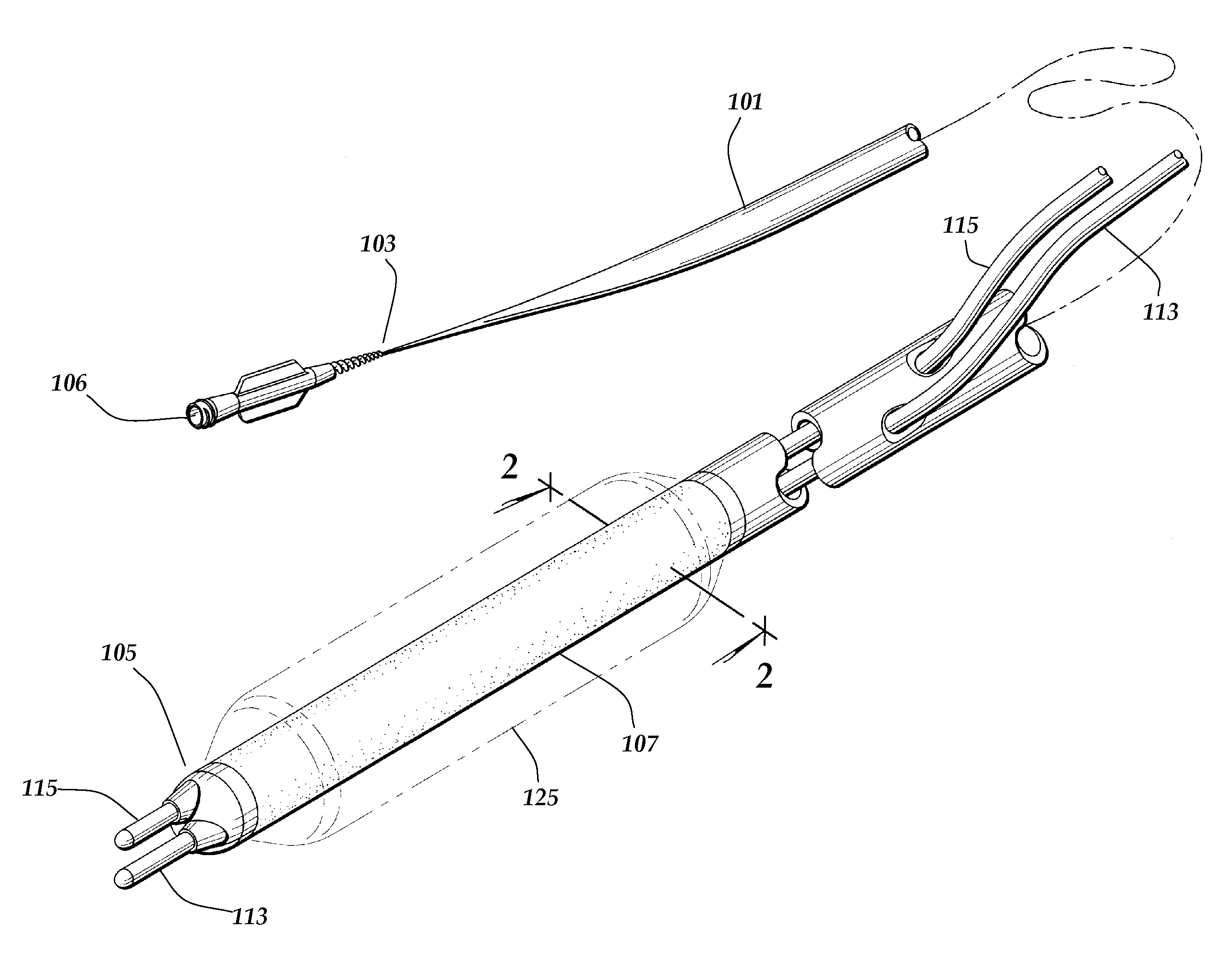
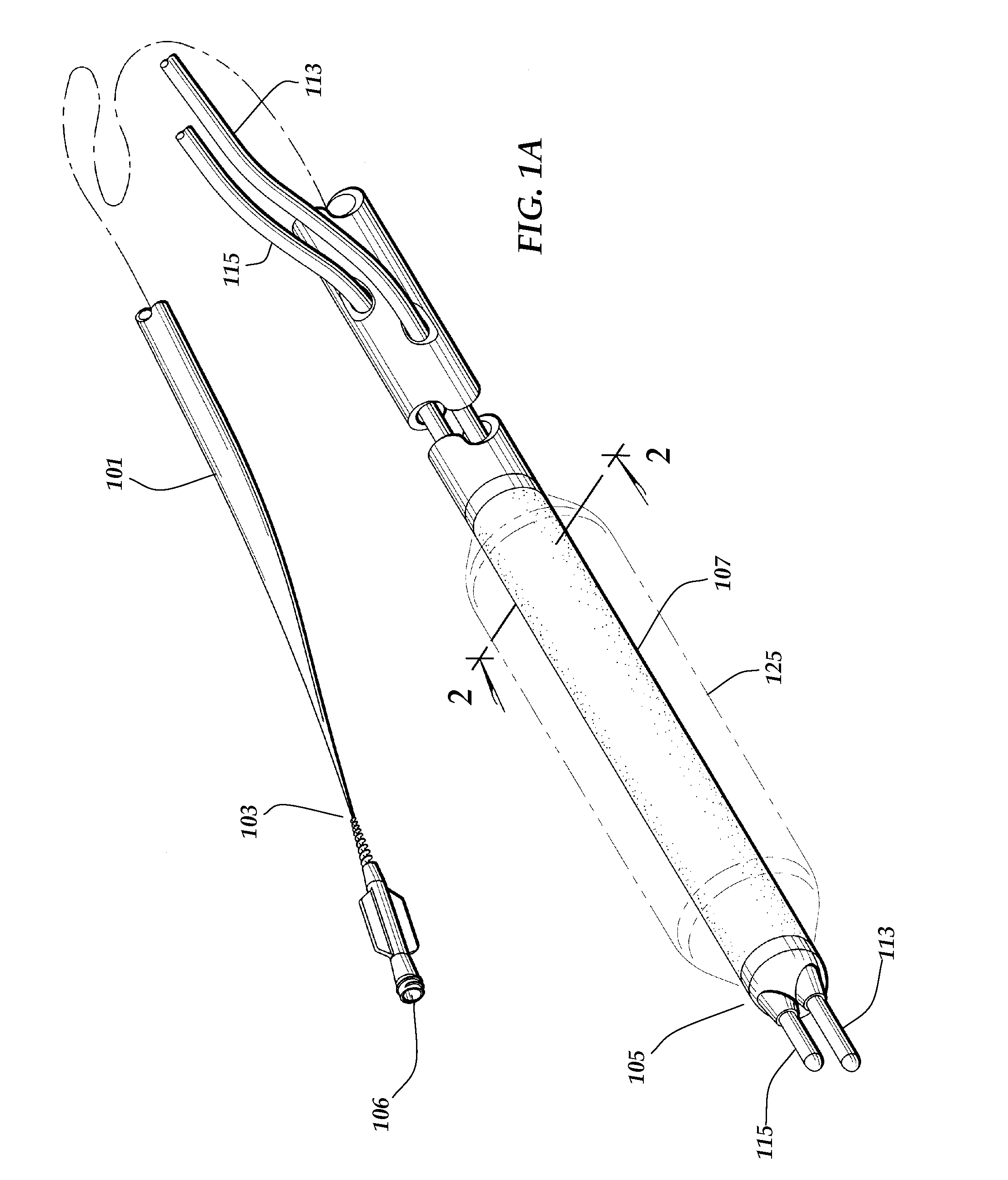
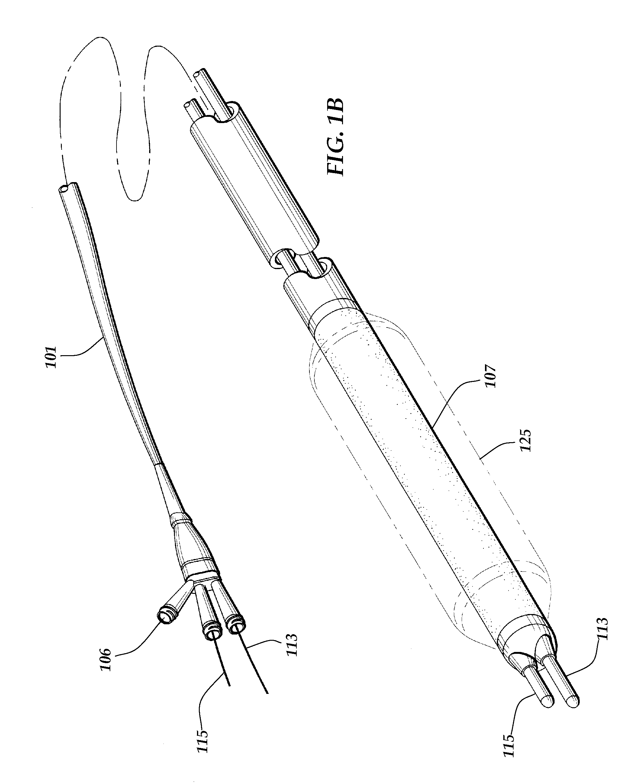
[0076]The catheter 101 may have various embodiments. As shown by FIG. 1A, one apparatus may comprise a catheter 101 having a guide wire 113 and a second guide wire 115 located at a very short distal end 105 immediately distal to an expandable member 107. The catheter has as well a proximal end 103, and such proximal end 103 is located closest to the physician performing the procedure. The catheter 101 may have an expandable member 107, typically a plastic balloon of various formulations, very near the distal end 105, and at the distal-most region of the catheter 101, there is a distal end 117 through which guide wire 113 and second guide wire 115 extend. The catheter 101 may preferably also have an expandable wire stent 109 (not shown in this figure) surrounding the expandable member 107. The expandable member 107 is actuated, or inflated, to a predetermined diameter, shown as the expandable member inflated diameter 125. The means for inflation to the expandable member inflated diam...


PUM


Abstract

Each arterial bifurcation lesion has a fingerprint-like pattern related to varying amounts of plaque and degree of obstruction in the main vessel proximal to, within the bifurcation itself, and the distal limbs of the main branch and side branch(es) and related to the angle of the bifurcation. A new device and with it a new technique is described to optimize treatment of bifurcation (and trifurcation) lesions. The invention and related method use a catheter capable of delivering two or more guide wires exiting at the distal end of the catheter allowing treatment of lesions more safely and efficaciously. Safety is increased by allowing both guide wires to remain in place throughout the entire procedure. Efficacy is increased, particularly in the long-term, by providing a result that maximizes vessel coverage and normal flow dynamics in the entire bifurcation area. Contemplated is the use not only of multiple guide wires but also modified balloon with a tapered design to optimize flow dynamics at the bifurcation in the final result.

Description

CROSS REFERENCES[0001]None.GOVERNMENTAL RIGHTS[0002]None.BACKGROUND OF THE INVENTION[0003]The bifurcation lesion, particularly in the coronary arteries, is a challenging lesion to treat percutaneously. Each bifurcation lesion has a fingerprint-like uniqueness.[0004]Treatment of bifurcation lesions is currently a topic of much investigation. Unlike most other lesion subsets utilizing bare-metal (BMS) and drug-eluting (DES) coronary stenting, the long-term results, particularly the incidence of restenosis, in either the main or subsidiary (side) branch vessel, after stenting the entire bifurcation are not necessarily better than stenting only the main branch and treating the subsidiary branch with balloon angioplasty. As such, provisional stenting, i.e., main branch stenting and stenting the side branch only when necessary, has been proposed as the preferred technique. Stenting of the side branch may be required in 30-50% of cases. There have been multiple methods proposed to treat bi...

Claims


Application Information

Patent Timeline
Patent Type & Authority Applications(United States)
IPC IPC(8): A61M25/00A61M25/16A61M29/00
CPCA61F2/86A61F2/954A61F2/958A61F2002/065A61M2025/0183A61M25/0105A61M25/1002A61M25/104A61M2025/004A61M25/0029
Inventor URETSKY, BARRY F.
Owner URETSKY BARRY F
Why Eureka
Try Eureka