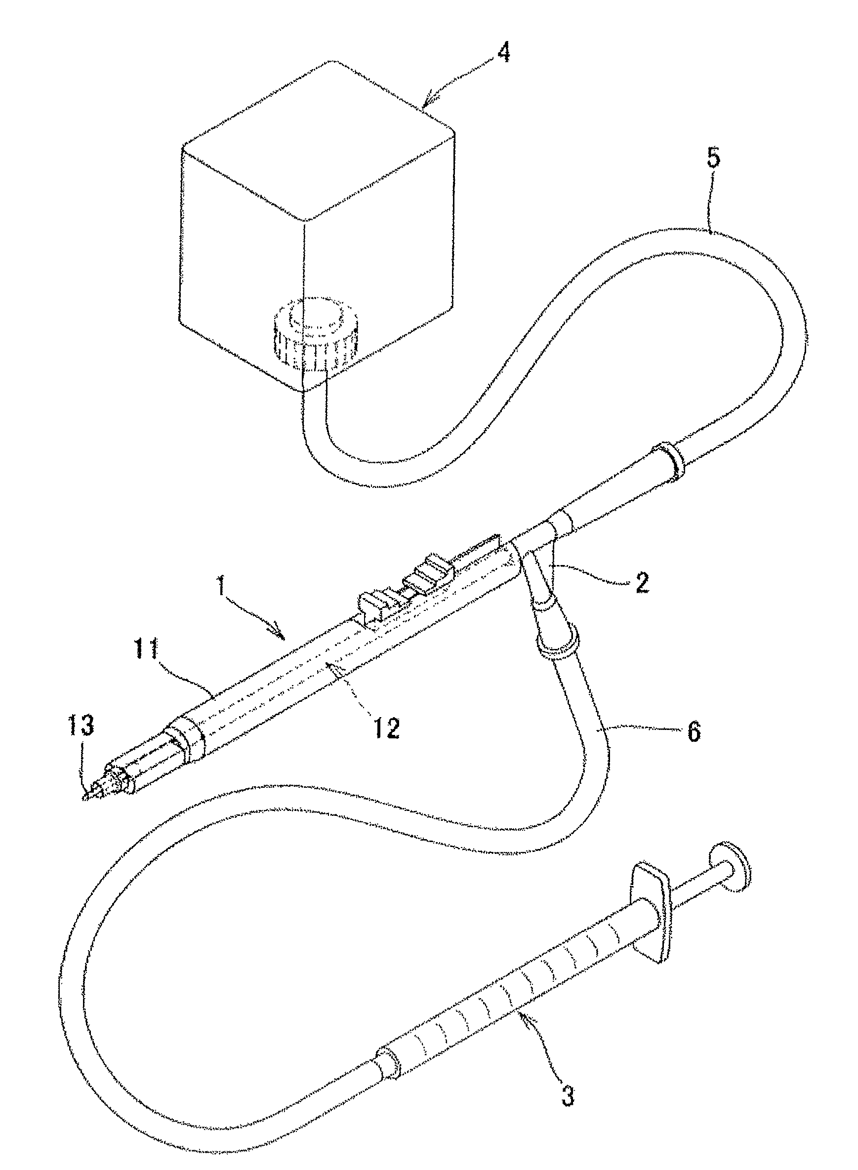
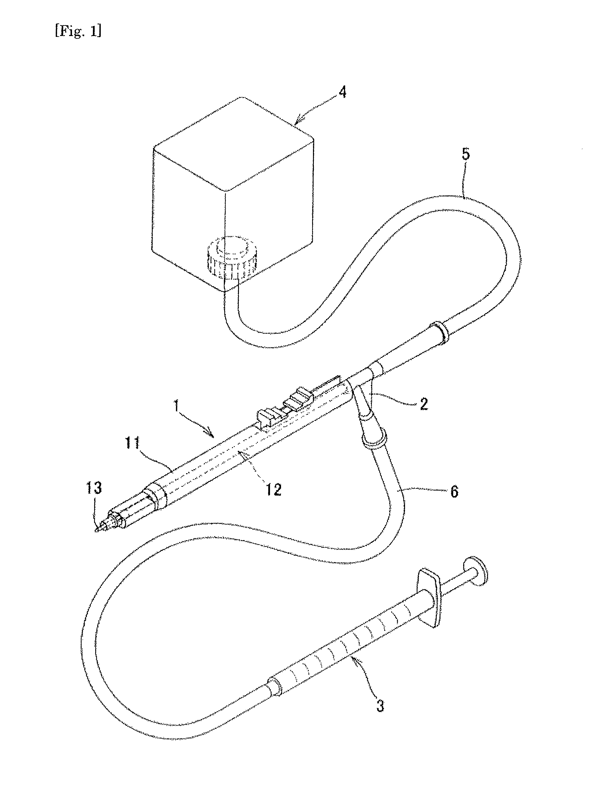
Injector for eye

an eye and injector technology, applied in the field of eye injectors, can solve the problems of low intraocular pressure, shallow anterior chamber, leakage of intraocular fluid, etc., and achieve the effect of easy insertion, no damage, and easy delivery

Inactive Publication Date: 2010-03-04
KANEKA CORP
View PDF8 Cites 34 Cited by
  • Summary
  • Abstract
  • Description
  • Claims
  • Application Information

AI Technical Summary

Benefits of technology

[0039]By the invention according to (1), a graft can be held in the space formed between the graft holding part included in the graft holding structure capable of being stored in the outer cylinder and the inner surface of the outer cylinder, and further the graft holding part is protruded from the outer cylinder by advancing the graft holding structure, so that the graft can be taken out from the outer cylinder. Thus, the graft can be easily inserted and stored in the outer cylinder without using tweezers or other gripping tools, so that the graft can be stored and protected in the injector for an eye without any damage. Furthermore, the graft can be inserted into an eyeball with the graft protected in the outer cylinder, then the graft holding structure is advanced to protrude from the outer cylinder and the graft can be taken out from the outer cylinder, so that the graft can be easily delivered to a transplant site in an eyeball.
[0040]By the invention according to (2), since the graft holding structure further includes the middle cylinder and the inner cylinder, the middle cylinder can push out the graft of the graft holding part by sliding of the middle cylinder with respect to the outer cylinder and / or sliding of the middle cylinder with respect to the inner cylinder, so that the graft can be more easily delivered to a transplant site in an eyeball.
[0041]By the invention according to (3), since the graft holding part includes the fluid discharge hole toward an inner surface of the graft, the graft held on the graft holding part can be more simply and reliably lifted up by the fluid to be delivered to a transplant site.
[0042]By the invention according to (4) to (6), since the injector for an eye includes the other discharge hole for liquid for keeping intraocular pressure or forming the anterior chamber, when the injector for an eye is inserted into an eyeball through a corneoscleral incision, reduction of an intraocular pressure or contraction of the anterior chamber caused by flowing out of intraocular fluid from the corneoscleral incision and the like can be prevented.
[0043]By the invention according to (7) to (10), since the injector for an eye includes the mechanism for relieving pressure in an eyeball (intraocular pressure), when the injector for an eye is removed at the state of a high intraocular pressure, the mechanism can effectively prevent that the graft delivered to the affected area becomes unstable as well as the pressure decreases.
[0044]By the invention according to (11), since the aperture for installing the graft in the outer cylinder which stores the graft holding part is formed on a side face of the outer cylinder and the side face is where the graft holding part is stored, and by the invention according to (12), since the opening and closing gate for sealing the aperture is included, the graft can be directly installed from the aperture into the injector for an eye (the outer cylinder). Thus, graft damage caused by inserting from an aperture at the leading end of the outer cylinder can be effectively prevented. Furthermore, it has the advantage that the transfer of both ways of the graft in the outer cylinder is shortened by omitting the transfer of one way. In addition, when the opening and closing gate is included, the graft installed in the outer cylinder can be protected from sudden trouble.

Problems solved by technology

Furthermore, when a graft is inserted into an eyeball (the anterior chamber), the corneoscleral incision must be enlarged with tweezers and the like, but at this time, sometimes intraocular fluid leaks out and the anterior chamber becomes shallow (an intraocular pressure becomes low).
However, even when these devices are used, a graft such as endothelial cells must be set in a medical device by using a grip tool and the like with the graft rolled, so that the risk of graft damage is still high.
Furthermore, since a graft is discharged into an eyeball with the graft rolled, the possibility that the graft is not thoroughly spread from the rolled state to be abnormally arranged to a transplant site is high.Patent Document 1: U.S. Patent Application Publication No. 2007 / 0208422 specification.Non-patent Document 1: Marianne O. Price, Francis W. Price, Ophthalmology, vol.

Method used


Image

  • Injector for eye
  • Injector for eye
  • Injector for eye

Examples


example 1

[0258]

[0259]Fresh piglet eyeballs were purchased from a public corporation for meat-packing and the inner layers of the corneal were carefully peeled. Then, the deep lamellar was punched using a trepan (a diameter of 8 mm) to prepare the sheet-shaped graft (the endothelial cell layer, the Descemet's membrane, and about ¼ of the corneal stroma).

[0260]1>

[0261]By using the injector for an eye #1 with a surface coating of polyethylene glycols shown in FIG. 33 (slidability: a rubber packing), the prepared graft was inserted into a piglet eyeball to deliver to backside of the cornea. In the following transplant Examples, the piglet eyeballs whose intraocular pressures were equally kept even when the eyeball walls were pressured with tweezers were used.

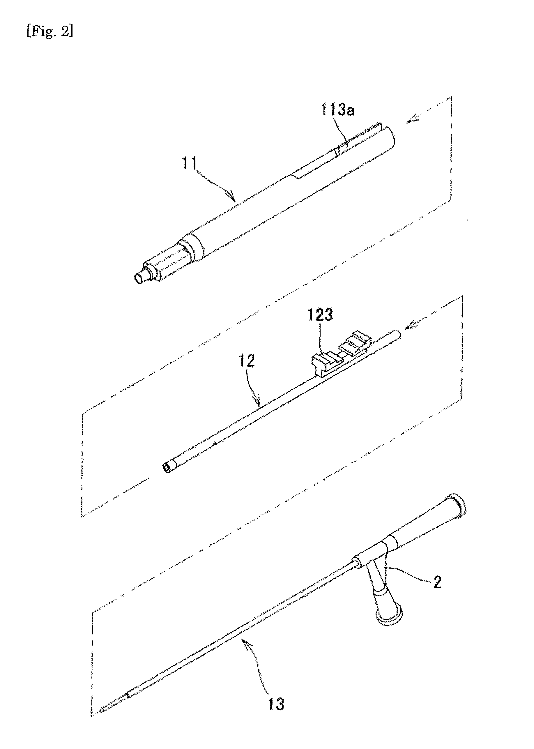
[0262]A small incision with a size of about 5 mm was made about 0.5 mm away from the corneal margin of the piglet eyeball to communicate with the anterior chamber. The graft was placed on the hinge structure of the outer cylinder (FIG. 34), ...

example 2

[0265]2>

[0266]By using the injector for an eye #2 with a surface lubricious coating of polyethylene glycols shown in FIG. 41 (slidability: a rubber packing), the prepared graft was inserted into the piglet eyeball to deliver to the backside of the cornea.

[0267]In the same manner as in Example 1, a small incision with a size of about 5 mm was made about 1 mm away from the corneal margin of the piglet eyeball to communicate with the anterior chamber. A drop of hyaluronic acid and a graft was placed on the graft holding part of the graft holding structure having the middle cylinder and the inner cylinder (FIG. 42), and the graft holding structure was slowly installed in the outer cylinder having a trumpet-shaped inner structure (FIGS. 43 and 44). Then, the graft holding structure was slid to slide the graft to the leading end of the outer cylinder.

[0268]The injector was pointed so that the major axis of the graft would be up with respect to the insert direction and the edge would be do...

example 3

[0270]3>

[0271]The insertion test was performed in the same manner as in Examples 1 and 2 except that the injector #3 was used. The injector #3 was the injector #1 having a surface without lubricious coating and its slidability was controlled by only each cylinder diameter (compliance). The obtained result was similar to those of Examples 1 and 2 (Table 1).

[0272]It was shown that the object can be achieved by even an untreated surface with lubricious coating and slide control with the cylinder diameter.


PUM


Abstract

[PROBLEMS] To provide an injector for ophthalmology which can guide an implant easily to an transplant place without causing any damage to the implant when the implant is inserted into an eyeball. [MEANS FOR SOLVING PROBLEMS] The injector for an eye used for inserting an implant into an eyeball comprises an outer tube, and an implant holding structure arranged in the outer tube to be slidable with respect to the outer tube. The implant holding structure has an implant holding portion which can be contained in the outer tube and forms a space for containing the implant between the implant holding portion and the inner surface of the outer tube when it is contained in the outer tube. The implant holding portion projects from the outer tube when the implant holding structure is advanced and the implant can be taken out from the outer tube.

Description

TECHNICAL FIELD[0001]The present invention relates to an ophthalmic medical device, and more particularly, an injector for an eye in order to deliver a graft to a transplant site and a system thereof.BACKGROUND ART[0002]The cornea is originally transparent, but when the corneal endothelial cell layer located a backside of the cornea becomes dysfunctional, edema or opacity sometimes occurs in the cornea to causes seriously impaired eyesight. The endothelial cell layer has the barrier function for protecting the corneal stroma from penetration of intraocular fluid (main components: collagen and proteoglycan) to some extent and the pump function for evacuating the penetrated intraocular fluid. When deterioration of the functions causes corneal hydrops, it is hard to transmit light. Specifically, a genetic factor (Fuchs' endothelial dystrophy), external factors such as cataract operation or corneal infection, the side effect by the laser therapy for glaucoma, or the long-term wearing of...

Claims


Application Information

Patent Timeline
Patent Type & Authority Applications(United States)
IPC IPC(8): A61F9/00
CPCA61B17/3468A61F9/0017A61F2/1662A61F2/143A61F9/007A61F2/148
Inventor IDE, TAKESHIYAMAMOTO, KAZUAKIFUKAYA, KOHEINAKANO, RYOJI
Owner KANEKA CORP
Why Eureka
Try Eureka