Reflector

Inactive Publication Date: 2010-03-11
ASTRIUM LTD
View PDF5 Cites 6 Cited by
  • Summary
  • Abstract
  • Description
  • Claims
  • Application Information

AI Technical Summary

Benefits of technology

[0012]The invention consequently provides a reflector antenna suitable for rejecting unwanted signals or minimising signal power to unwanted receivers. The stepped profile produces a sharp, deep region of near-zero field strength which is robust in the presence of reflector surface or feed pattern errors. The location of the near-zero field strength can subsequently be steered by moving the reflector only. The antenna assembly may comprise a positioning mechanism for steering the reflector to reposition the location of the near-zero directivity. The location of the near-zero directivity can also be steered by adjusting the amplitude and phase of an additional low resolution beam covering the same region. Accordingly, the antenna assembly may further comprise a horn for producing a beam that covers the same region as the antenna, the horn being controllable to adjust the amplitude and phase of the beam for repositioning the location of the near-zero field strength.

Problems solved by technology

Especially, satellite communication can be degraded or interrupted by interfering signals.
Some interference is accidental and due to faulty ground equipment.
Other interference is intentional and malicious.
A problem with this approach is that quadratic cancellation patterns are sensitive to random surface errors of the reflector and to errors in the feed pattern as shown in FIGS. 8b and 9b.

Method used


Image

  • Reflector
  • Reflector
  • Reflector

Examples


Embodiment Construction

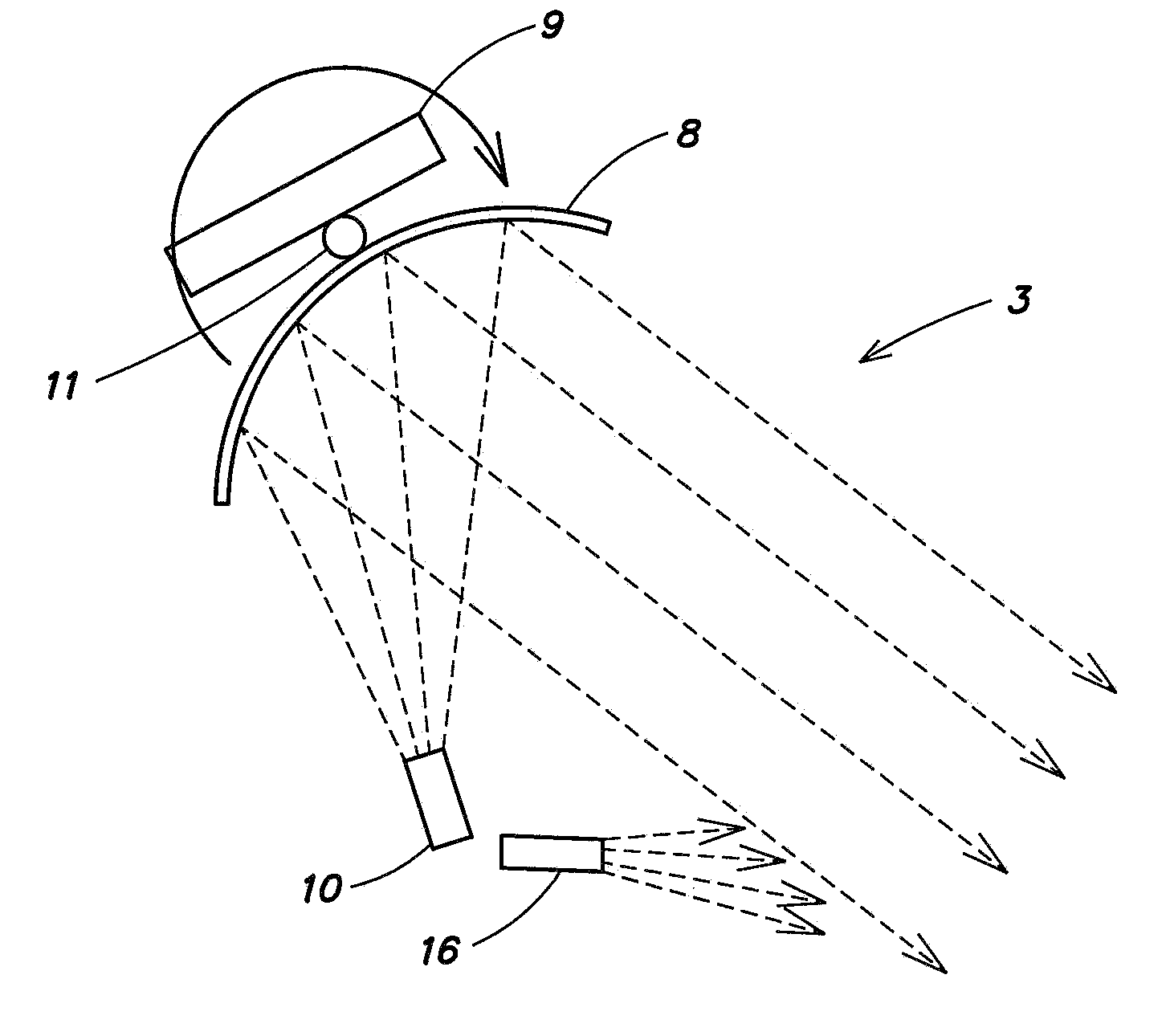
[0030]With respect to FIG. 3, a satellite payload 1 comprises a communication system comprising a receive antenna 2 and a transmit antenna 3. The receive antenna comprises a reflector 4 movably mounted on a frame 5, a feed 6 for receiving the radiation reflected off the reflector 4 and a positioning module 7 for rotating the reflector 4. Similarly, the transmit antenna 3 comprises a reflector 8 rotatable mounted on a frame 9, a feed 10 for generating a beam of electromagnetic radiation for reflection off the reflector 4 and a positioning module 11 for rotating the reflector 4. The satellite payload also comprises a receive signal processing unit 12 for demodulating the received signal, a controller 13 for processing the data and controlling the positioning modules, a transmit signal processing unit 14 for modulating the signal to be transmitted and a memory 15 for storing data and instructions for controlling the reflectors and feeds. Optionally, the controller 13 may be located rem...


PUM


Abstract

A reflector for a reflector antenna is provided for producing a far field pattern with near-zero field strength at a predetermined position, the reflector having a surface comprising a stepped profile for generating the near-zero field strength. The stepped profile may comprise a radial step. The location of the near-zero field strength can be steered by moving the reflector only or by adjusting the amplitude and phase of an additional low resolution beam, produced by, for example, a simple horn, covering the same region.

Description

FIELD OF THE INVENTION [0001]The invention relates to a reflector for a reflector antenna for producing a far field radiation pattern having near-zero field strength in a predetermined region.BACKGROUND OF THE INVENTION [0002]Satellite communication has become an important part of our overall global telecommunication infrastructure. Satellites are being used for business, entertainment, education, navigation, imaging and weather forecasting. As we rely more and more on satellite communication, it has also become more important to protect satellite communication from interference and piracy. There is now a demand from commercial satellite operators for satellite antennas that provide rejection of unwanted signals or minimise signal power to unwanted receivers.[0003]Especially, satellite communication can be degraded or interrupted by interfering signals. Some interference is accidental and due to faulty ground equipment. Other interference is intentional and malicious. By directing a...

Claims


Application Information

Patent Timeline
IPC IPC(8): H01Q15/14H01Q3/20H01Q13/02
CPCH01Q1/288H01Q3/02H01Q25/00H01Q15/16H01Q19/10H01Q3/2611
Inventor ROBSON, DAVIDSTIRLAND, SIMON JOHN
Owner ASTRIUM LTD
Why Eureka
Try Eureka