Method and apparatus for liquid precursor atomization

a liquid precursor and atomization technology, applied in the direction of flow mixers, combustion air/fuel air treatment, chemical vapor deposition coating, etc., can solve the problems of reducing the thermal decomposition of the liquid phase at sufficiently high temperatures, reducing the thermal decomposition of the liquid phase, and many modern precursor chemicals are difficult to vaporize. , to achieve the effect of avoiding excessive heating

Active Publication Date: 2010-03-18
MSP
View PDF19 Cites 14 Cited by
  • Summary
  • Abstract
  • Description
  • Claims
  • Application Information

AI Technical Summary

Benefits of technology

[0006]The present disclosure relates to an apparatus for atomizing a precursor liquid for vapor generation and thin film deposition on a substrate. The precursor liquid is atomized by a carrier gas to form a droplet aerosol comprised of small precursor liquid droplets suspended in the carrier gas. The droplet aerosol is then heated to form vapor, producing a gas/vapor mixture that can be introduced into a deposition chamber to form thin films on a substrate. The liquid is introduced into the atomizing apparatus in such a manner as to avoid excessive heating that can occur or lead to the formation of undesirable by-products due to material degradation as result of thermal decomposition. The apparatus is particu

Problems solved by technology

Contact between the precursor liquid and a hot metal surface can cause the precursor to thermally decompose to form undesirable by products.
In addition, due to the evaporative cooling effect, the surface temperature of an evaporating droplet remains low, further reducing thermal decomposition that can occur in the liquid phase at sufficiently high temperatures.
While droplet vaporization has been used successfully in recent years to vaporize precursor chemicals for semiconductor device fabrication, many modern precursor chemicals are difficult to vaporize.
The problem of the

Method used


Image

  • Method and apparatus for liquid precursor atomization
  • Method and apparatus for liquid precursor atomization
  • Method and apparatus for liquid precursor atomization

Examples


Embodiment Construction

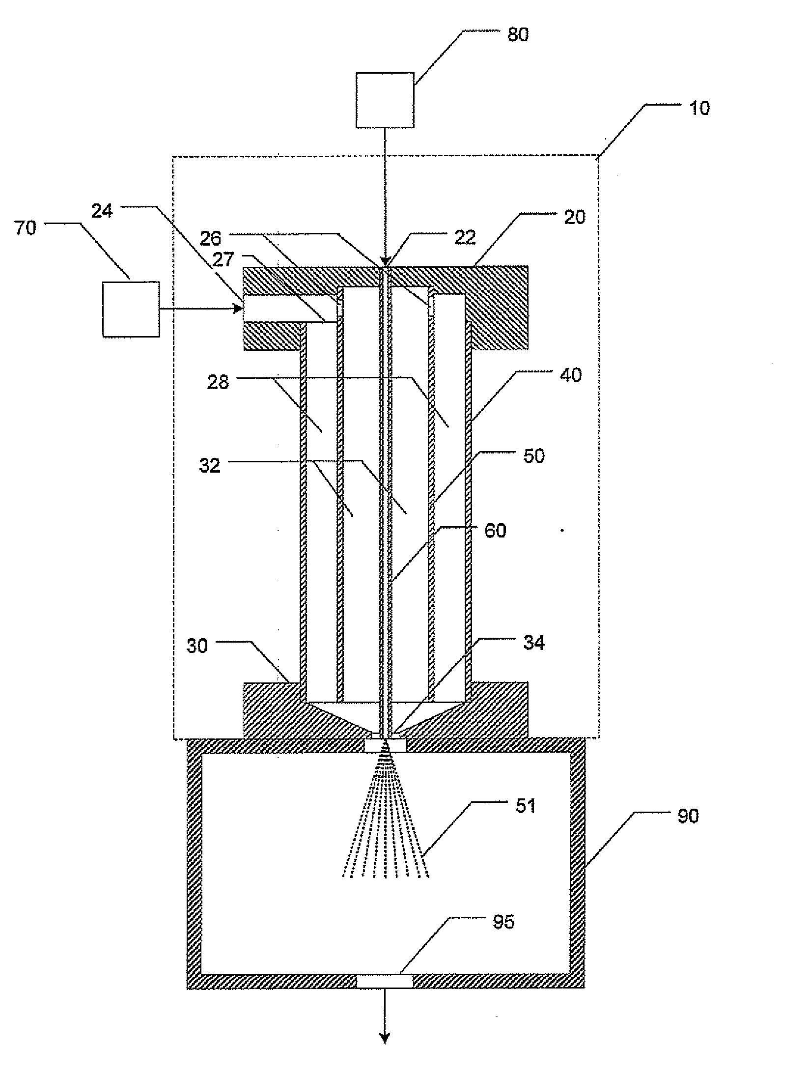
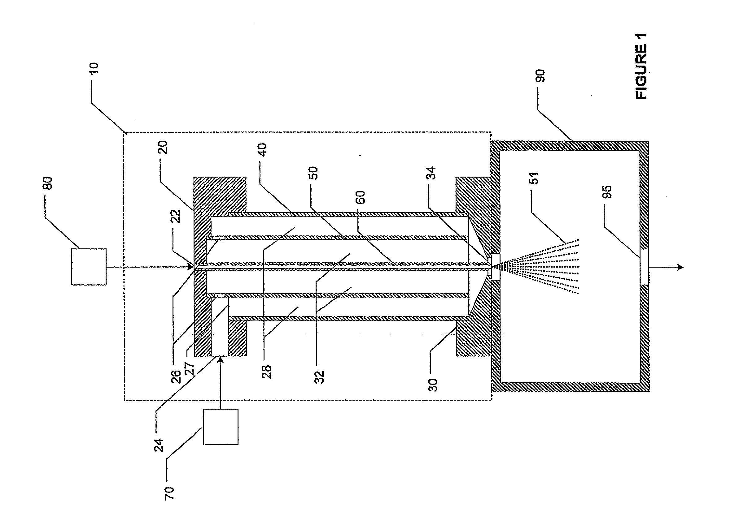
[0010]FIG. 1 is a schematic diagram of one embodiment of the atomization apparatus. Like reference characters will be used for like elements throughout the Figures. The atomization apparatus is shown generally at 10. It is provided with a liquid source 80 containing a precursor chemical to be vaporized, and a gas source 70 containing a carrier gas used for atomizing the liquid to form a droplet aerosol for vaporization. The atomization apparatus 10 is connected to a heated vaporization chamber 90 in which the droplet aerosol 51 produced by the atomization apparatus 10 is vaporized to form a gas / vapor mixture. The resulting gas / vapor mixture then flows out of the vaporization chamber through outlet 95 into a deposition chamber (not shown) for thin film deposition and / or semiconductor device fabrication.

[0011]The atomization apparatus 10 is provided with a header 20 with a liquid inlet 22 for the precursor liquid from source 80 to enter, and a gas inlet 24 for the carrier gas from gas...


PUM

PropertyMeasurementUnit
Temperatureaaaaaaaaaa
Thicknessaaaaaaaaaa

Abstract

An apparatus for atomizing a precursor liquid for vapor generation and thin film deposition on a substrate. The precursor liquid is atomized by a carrier gas to form a droplet aerosol comprised of small precursor liquid droplets suspended in the carrier gas. The droplet aerosol is then heated to form vapor, producing a gas/vapor mixture that can be introduced into a deposition chamber to form thin films on a substrate. The liquid is introduced into the atomizing apparatus in such a manner as to avoid excessive heating that can occur or lead to the formation of undesirable by-products due to material degradation as result of thermal decomposition. The apparatus is particularly suited for vaporizing high molecular weight substances with a low vapor pressure that requires a high vaporization temperature for the liquid to vaporize. The apparatus can also be used to vaporize solid precursors dissolved in a solvent for vaporization.

Description

CROSS-REFERENCE TO RELATED APPLICATION[0001]The present application is based on and claims the benefit of U.S. provisional patent application Ser. No. 61 / 096,384, filed Sep. 12, 2008, the content of which is hereby incorporated by reference in its entirety.BACKGROUND OF THE DISCLOSURE[0002]Thin film deposition on a substrate for semiconductor device fabrication and other applications is frequently accomplished through a gas phase process using a gas / vapor mixture containing the precursor vapor needed for film formation. The mixture is usually introduced into a deposition chamber under suitable temperature and pressure conditions to form a thin film on the substrate. In the case of a precursor in liquid form, the precursor vapor can be generated by heating the liquid to a suitably high temperature. A carrier gas can then be bubbled through the liquid to saturate the gas with vapor to form the desired gas / vapor mixture. Alternatively, vapor can be generated by injecting the liquid dir...

Claims


Application Information

Patent Timeline
IPC IPC(8): B01F3/04
CPCB05B7/0475B05B7/066Y10S261/65B05B7/1686B05B7/168H01L21/02H01L21/205
Inventor LIU, BENJAMIN Y.H.
Owner MSP
Why Eureka
Try Eureka