
Wireless network

a wireless network and wireless technology, applied in the field of wireless networks, can solve the problems of legacy devices, easy overflow of wireless mediums, and inability of wireless devices to grant priority to wireless mesh networks or access points, etc., and achieve the effect of improving the utilization capacity of one or more wireless channels and improving performan

Inactive Publication Date: 2010-03-18
KONINKLIJKE PHILIPS ELECTRONICS NV
View PDF8 Cites 6 Cited by
  • Summary
  • Abstract
  • Description
  • Claims
  • Application Information

AI Technical Summary

Benefits of technology

[0003]It is an object of the invention to provide a wireless network, and a method and device for such a wireless network with an improved performance, especially with an improved utilization of the capacity of one or more wireless channels.

Problems solved by technology

However, wireless devices may not grant priority to wireless mesh networks or the access points to which they are associated.
Hence, without any means of flow control or congestion avoidance, legacy devices, which are non-mesh devices, may easily overload the wireless medium.
As a result, frames cannot be delivered and legacy devices retry frame transmission.
Since the mesh devices usually cannot directly signal to the associated devices to reduce frame generation, the wireless medium is easily overloaded.
Then, with a congested wireless medium, the mesh network cannot forward data.
As a result, frame losses may occur and higher layer protocols may try to resend the lost data so that the situation becomes even worse.
But, when the receiver address also equals the address of the device that transmits the request to send, then in normal operation no device answers.

Method used


Image

  • Wireless network
  • Wireless network
  • Wireless network

Examples


Embodiment Construction

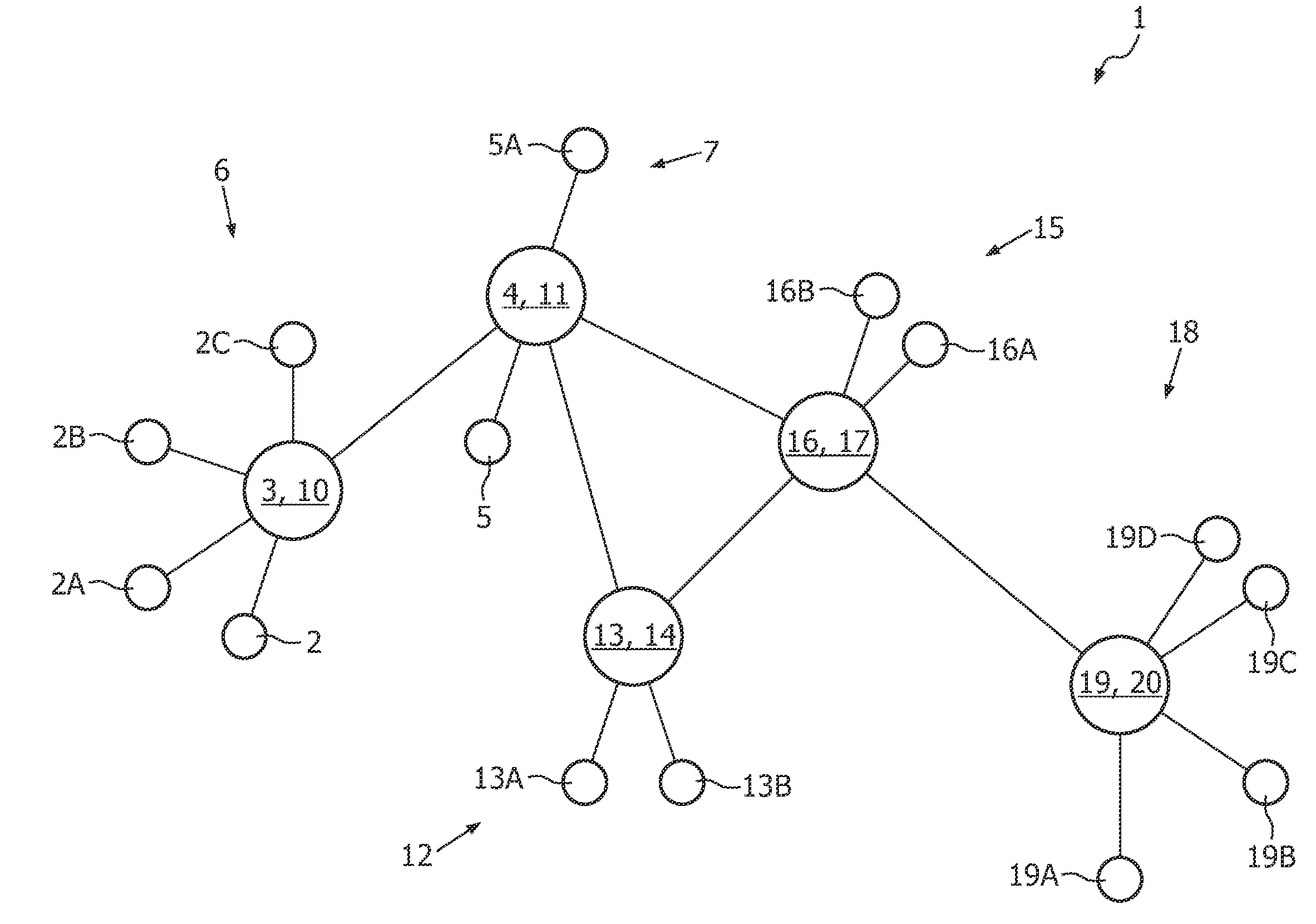
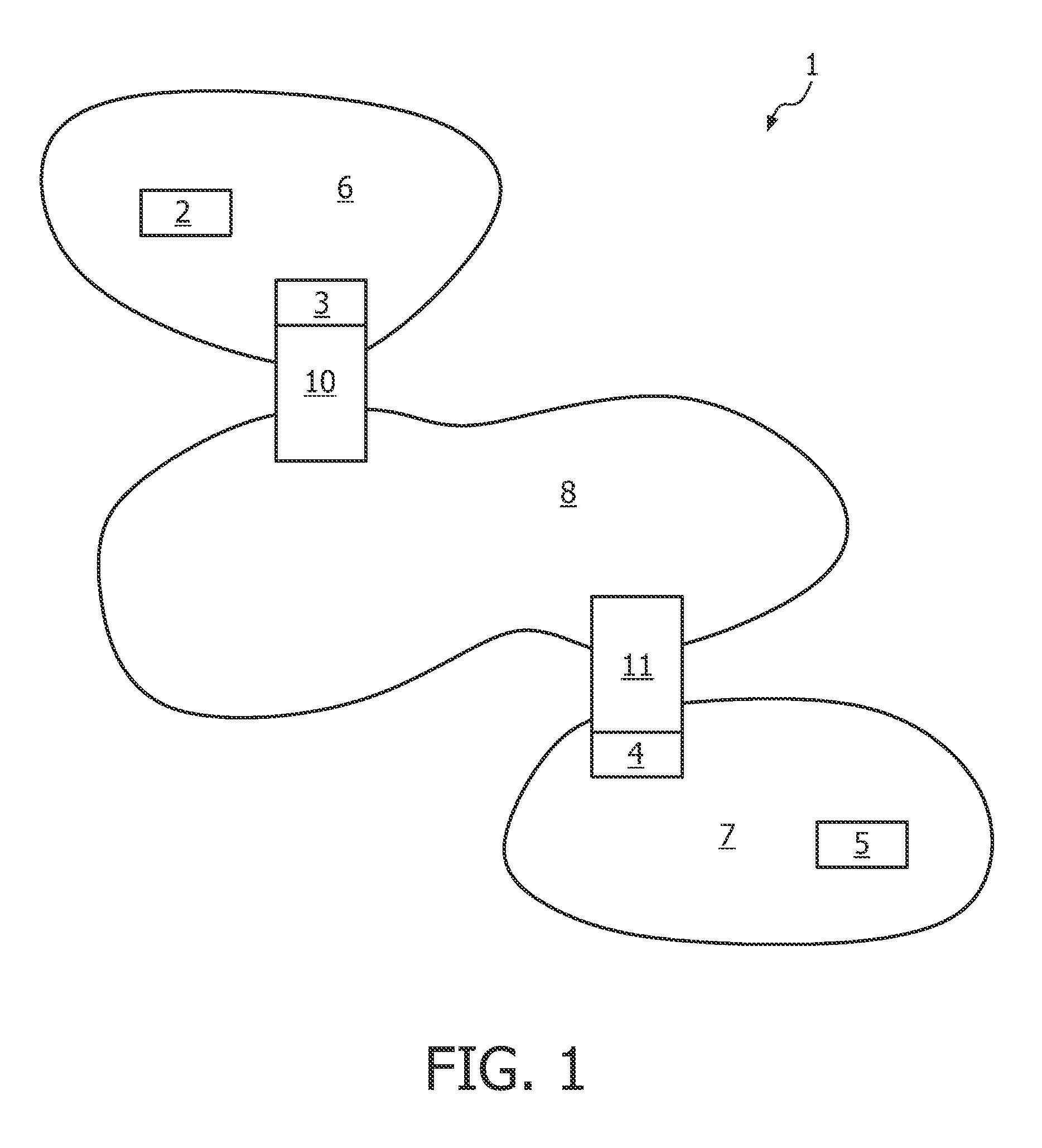
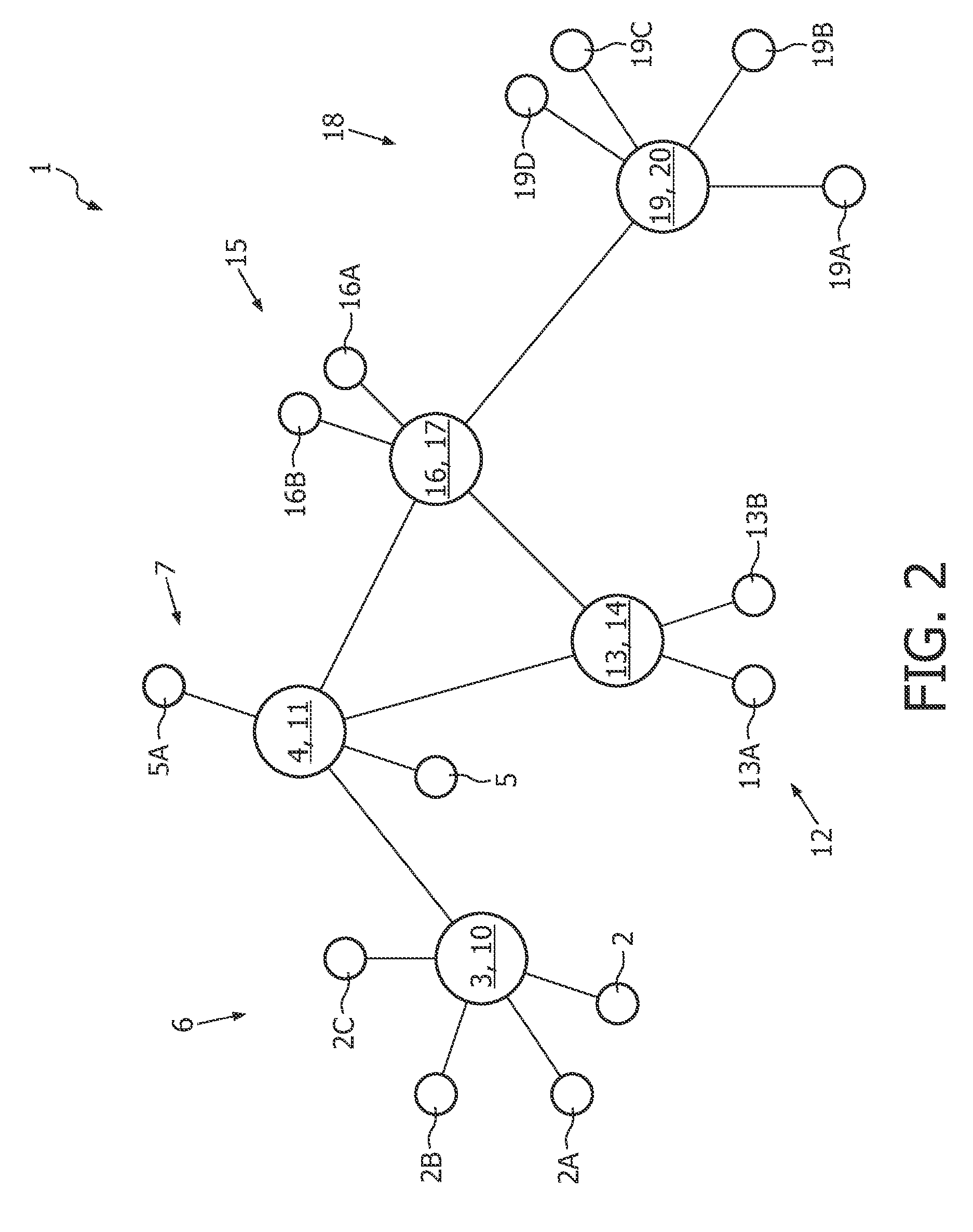
[0020]FIG. 1 shows a schematic structure of a wireless network 1 according to an embodiment of the invention. The wireless network 1 can be used for networks according to a standard such as ANSI / IEEE Std 802.11 and further developments such as IEEE 802.11s ESS. The wireless network 1 and the method for the wireless network 1 are applicable but not limited to wireless local area networks (WLAN). The wireless network 1 and the method for the wireless network 1 may be a part or built up a wireless communication system. Thereby, the wireless network 1 may also be combined with other networks, which can be wireless or wireline networks.

[0021]The addressable units of the wireless network 1 are stations 2, 3, 4, 5. Each of the stations 2 to 5 is a message destination, but not, generally, a fixed location. The stations 2 to 5 may be mobile or portable, wherein a portable one is moved from location to location, but is only used while at a fixed location, and a mobile one actually makes acces...


PUM


Abstract

A wireless network (1) comprises basic service sets (6, 7) and a distribution system (8). Each of the basic service sets (6, 7) comprises stations (2, 3) and stations (4, 5), respectively. Thereby, data is moved between their basic service sets (6, 7) and said distribution system (8) via access points (10, 11), which are also stations (3, 4). A medium access control architecture incorporating a distributed coordination function as an access method is provided. Thereby, a normal mode and a mesh mode are provided. Thereby, normal mode is used to transmit data between stations (2, 3; 4, 5) within each of the basic service sets (6; 7). In mesh mode, data is transmitted between the access points (10, 11). To priorize transmission within the distribution system (8) the stations (2, 5), which are not mesh devices, are silence during mesh mode. Therefor, one of the access points (10, 11) sends a request to send in which the address of the access point (10, 11) is used as both the transmitter address and the receiver address of this request to send.

Description

FIELD OF THE INVENTION[0001]The present invention relates to a wireless network comprising a medium access control architecture and to a method for such an wireless network. More particularly, the present invention relates to a wireless network on the basis of a standard such as a standard from the family of IEEE 802 standards, especially ANSI / IEEE Std 802.11.BACKGROUND OF THE INVENTION[0002]In a wireless network the wireless medium is shared among several devices. With cheap devices only a single radio is available. Further, in dense populated areas, only a single frequency channel may be available. A wireless mesh network may help to extend the range of a wireless network and provide seamless coverage. In case of a single frequency channel, stations and entities of the wireless mesh network share the same channel of the wireless medium. However, the wireless mesh network carries the aggregated traffic of all stations. This may result in a poor performance or a reduced reliability ...

Claims


Application Information

Patent Timeline
Patent Type & Authority Applications(United States)
IPC IPC(8): H04W4/00
CPCH04W8/26H04W88/10H04W74/08H04W74/004
Inventor DENTENEER, THEODORUS JACOBUS JOHANNESHIERTZ, GUIDO ROLANDMAX, GUSTAF SEBASTIANWALKE, BERNHARD
Owner KONINKLIJKE PHILIPS ELECTRONICS NV
Learn More