
Circuit arrangement

a technology of circuits and components, applied in the field of circuit arrangements, can solve the problems of high hardware complexity, increasing error frequency, and relatively often inability to function circuits,

Inactive Publication Date: 2010-03-18
UNIV POSTDAM
View PDF8 Cites 4 Cited by
  • Summary
  • Abstract
  • Description
  • Claims
  • Application Information

AI Technical Summary

Benefits of technology

[0015]The object of the invention is to create a circuit arrangement which is as simple as possible, with a functional circuit which comprises at least one combinatorial circuit part, and also with error correction and error detection, in which soft errors in registers can be corrected and also errors during operation in the at least one combinatorial circuit part, the registers and corrected output values can be detected in the best possible manner.
[0022]The circuit arrangement makes it possible to omit the need for special controllable memory elements with different modes of operation. In particular, it is also not necessary for there to be a special scan mode or a mode for debugging. The complexity of error detection can be adapted to the required certainty of error detection, for example by using different error-detecting codes.

Problems solved by technology

Due to the high degree of integration of electronic circuits, the frequency of errors is increasing.
If errors occur relatively frequently in electronic circuits, then it is particularly disadvantageous that the errors cannot be corrected by the error detection circuit, and therefore the circuit is relatively often not capable of functioning due to its errors.
One particular disadvantage here is the fact that the necessary hardware complexity is high and that only relatively few errors can be corrected when using an error-correcting code.
Due to the high degree of integration of electronic circuits, the susceptibility to errors and the frequency of errors is increasing with regard to non-permanent or transient errors.
These errors may lead to “soft errors” in the memory elements.
More frequently, a soft error occurs in a memory element directly, wherein the memory element may be a latch or a flip-flop, such an error being caused for example by radiation.
If, on the other hand, a transient error exists in the combinatorial circuit part and the logical, electrical and temporal conditions are met, then the incorrect data input at the input of a memory element is accepted by the memory element and the state of the memory element is incorrect for the entire cycle.
It can be seen that the memory elements known as “scan-out flip-flops” are relatively complicated.
They are operated in various modes which are selected via control lines and special control signals, which is complicated.
It is disadvantageous that errors in the combinatorial circuit parts of the circuit cannot be detected, since errors in the combinatorial circuit always lead to identical values in the duplicate latches of the memory elements.
Errors in the corrected values further processed or output by the circuit and in the C-elements used also cannot be detected, so that the correctness of the corrected values cannot be checked, which is also disadvantageous.

Method used


Image

  • Circuit arrangement
  • Circuit arrangement
  • Circuit arrangement

Examples


Embodiment Construction

OF EMBODIMENTS OF THE INVENTION

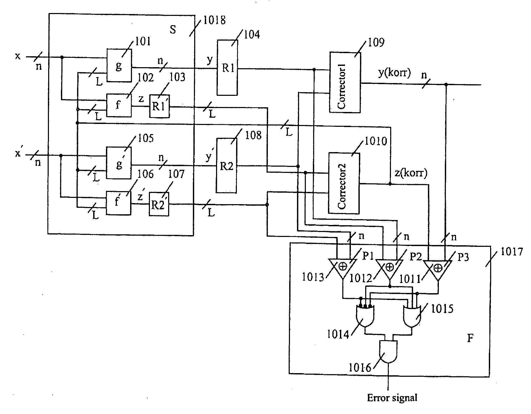
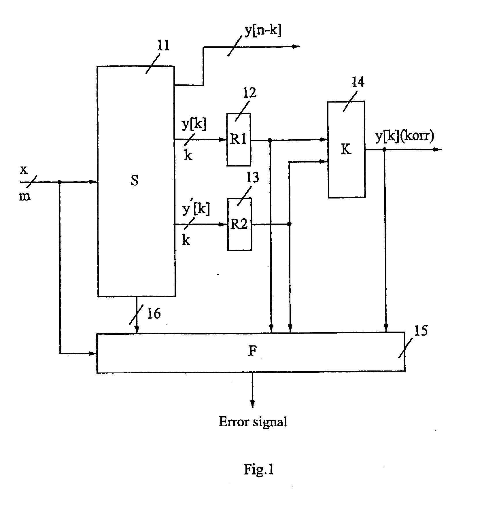
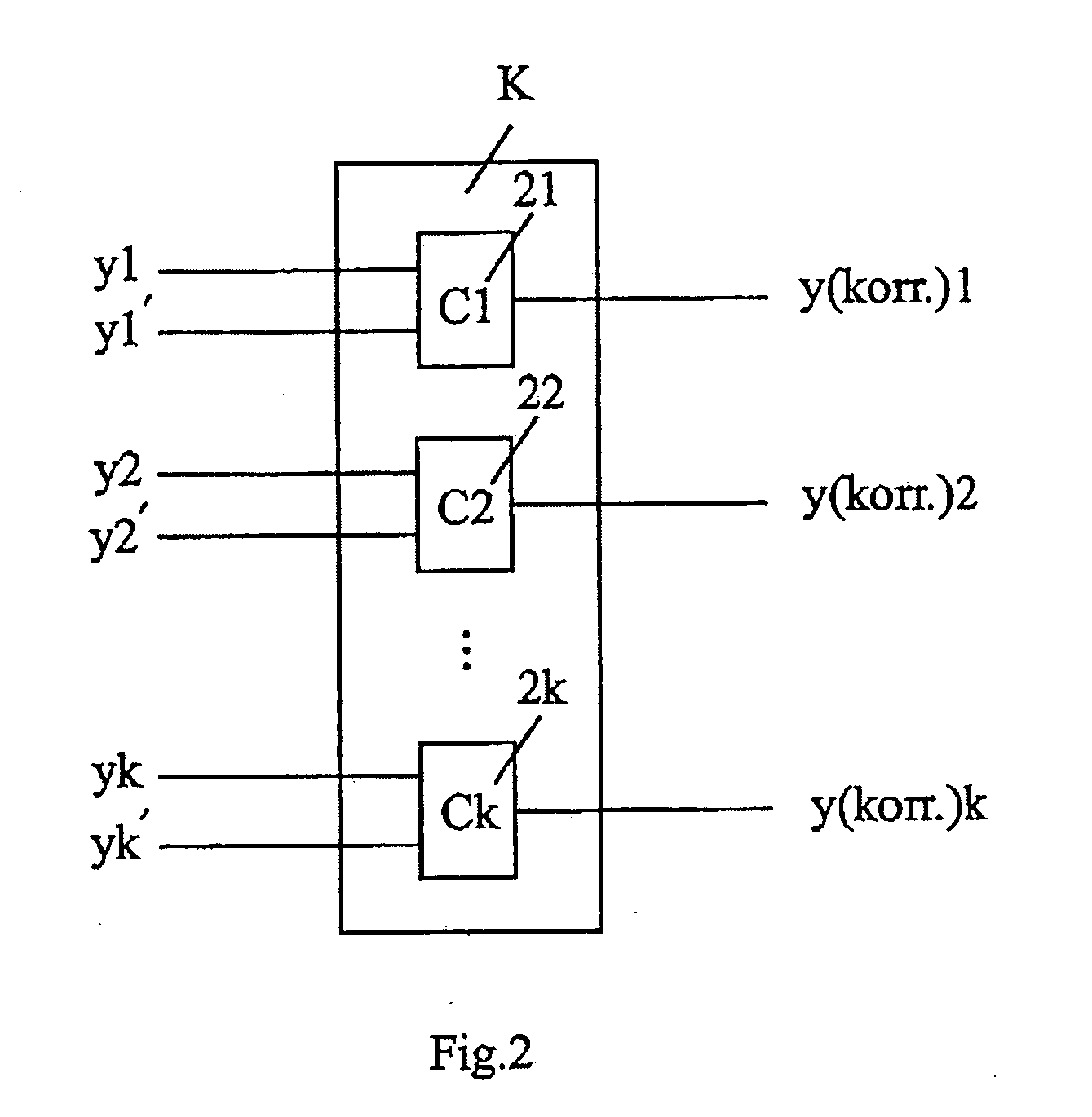
[0053]The invention will be explained in more detail below on the basis of preferred examples of embodiments and with reference to figures, in which:

[0054]FIG. 1 shows a circuit arrangement for correction and error detection for a functional circuit;

[0055]FIG. 2 shows a corrector composed of C-elements with 2k inputs and k outputs;

[0056]FIG. 3 shows an implementation of a C-element composed of transistors in CMOS;

[0057]FIG. 4 shows the table of values for a C-element;

[0058]FIG. 5 shows a circuit arrangement for correction and error detection for a combinatorial circuit using a separable error-detecting code;

[0059]FIG. 6 shows an error detection circuit using a parity code;

[0060]FIG. 7 shows a circuit arrangement for a particular combinatorial circuit;

[0061]FIG. 8 shows a circuit arrangement for a particular combinatorial circuit, in which parts of the functional circuit and of the error detection circuit are used in common;

[0062]FIG. 9 shows a circuit ...


PUM


Abstract

The invention relates to a circuit arrangement, comprising: a functional circuit with m (m=1, 2, . . . ) data inputs and n (n=1, 2, . . . ) data outputs for processing at least one m-dimensional binary data input (x1, . . . , xm) to form an n-dimensional data output (y1, . . . , yn), wherein the functional circuit comprises at least one combinatorial circuit part, at least two registers with a word length k (k=1, 2, . . . ; k≦n) which are coupled to at least some of the n data outputs of the functional circuit in order to store output values (y=y1, . . . , yk; y′=y′1, . . . , y′k) which are duplicated with respect to one another or are duplicated with bit-by-bit inversion with respect to one another, said output values being derived from the n-dimensional data output (y1, . . . , yn) of the functional circuit, at least one corrector with an input word length 2k and an output word length k, which is coupled to data outputs of the at least two registers and supplies a k-dimensional corrected data output (y[k](korr)=y1(korr), . . . , yk(korr)), and an error detection circuit for detecting errors during operation of at least one of the aforementioned circuit elements: the functional circuit, the at least two registers and the corrector.

Description

[0001]The invention relates to the field of error detection and error correction in digital circuits.BACKGROUND OF THE INVENTION[0002]Due to the high degree of integration of electronic circuits, the frequency of errors is increasing. It is known to monitor digital circuits for example by duplication and comparison, by using codes and generally by means of error detection circuits (cf. Goessel et al. “Error Detecting Circuits”, McGrawHill, 1994; Rao et al. “Error Control Coding for Computer Systems”, Prentice Hall, 1989).[0003]An error detection circuit is used to detect an error in the circuit to be monitored. If errors occur relatively frequently in electronic circuits, then it is particularly disadvantageous that the errors cannot be corrected by the error detection circuit, and therefore the circuit is relatively often not capable of functioning due to its errors.[0004]It is also known to use error-correcting circuits to correct the errors which occur. For instance, it is known ...

Claims


Application Information

Patent Timeline
Patent Type & Authority Applications(United States)
IPC IPC(8): G06F11/07G06F11/10H03M13/00
CPCG06F11/10G11C29/32
Inventor GOESSEL, MICHAELSOGOMONYAN, EGORMARIENFELD, DANIEL
Owner UNIV POSTDAM
Learn More