
Methods and devices for providing mechanical ventilation with an open airway interface

a technology of open airway and mechanical ventilation, applied in the field of ventilation therapy, can solve the problems of limiting the additive volume that can be delivered to the lung, system ineffectiveness, and inability to provide mechanical ventilation support to the lungs, so as to reduce the work of breathing and enhance mobility

Active Publication Date: 2010-03-25
BREATHE TECHNOLOGIES INC
View PDF102 Cites 100 Cited by
  • Summary
  • Abstract
  • Description
  • Claims
  • Application Information

AI Technical Summary

Benefits of technology

[0011]Embodiments of the present invention may also include that the ventilator gas is delivered as a volume synchronized with the patient's inspiratory cycle, in which the volume is selected by the user. The ventilator gas may be delivered continuously, cyclically at a rate determined by the ventilator, as a volume cyclically synchronized with the patients breathing, and with a back up rate to deliver a mandatory number of breaths over a period of time, or as a volume cyclically during an inspiratory cycle to reduce the work of breathing, and during an expiratory cycle to create PEEP. The system may be used to treat a lung disease, a breathing disorder, or a neuromuscular disorder. The system may be used with a portable gas supply and used to enhance mobility. The patient interface may be an airway tube, tracheostomy tube, a T-tube, and stomal stent, a stoma, an endotracheal tube, a trans-cricothryoid tube, a trans-laryngectomy tube, a mask, a nasal mask, an oral mask, a nasal-oral mask, a cannula, a transtracheal cannula, a nasal cannula, an oral cannula, or a nasal-pharyngeal cannula.

Problems solved by technology

In OAV, providing mechanical ventilation support to the lungs is not obviously possible, because air delivered from the ventilator has the potential of leaking out of the upper airway if the airway is open, thus rendering the system ineffective and limiting the additive volume that can be delivered to the lung.

Method used


Image

  • Methods and devices for providing mechanical ventilation with an open airway interface
  • Methods and devices for providing mechanical ventilation with an open airway interface
  • Methods and devices for providing mechanical ventilation with an open airway interface

Examples


Embodiment Construction

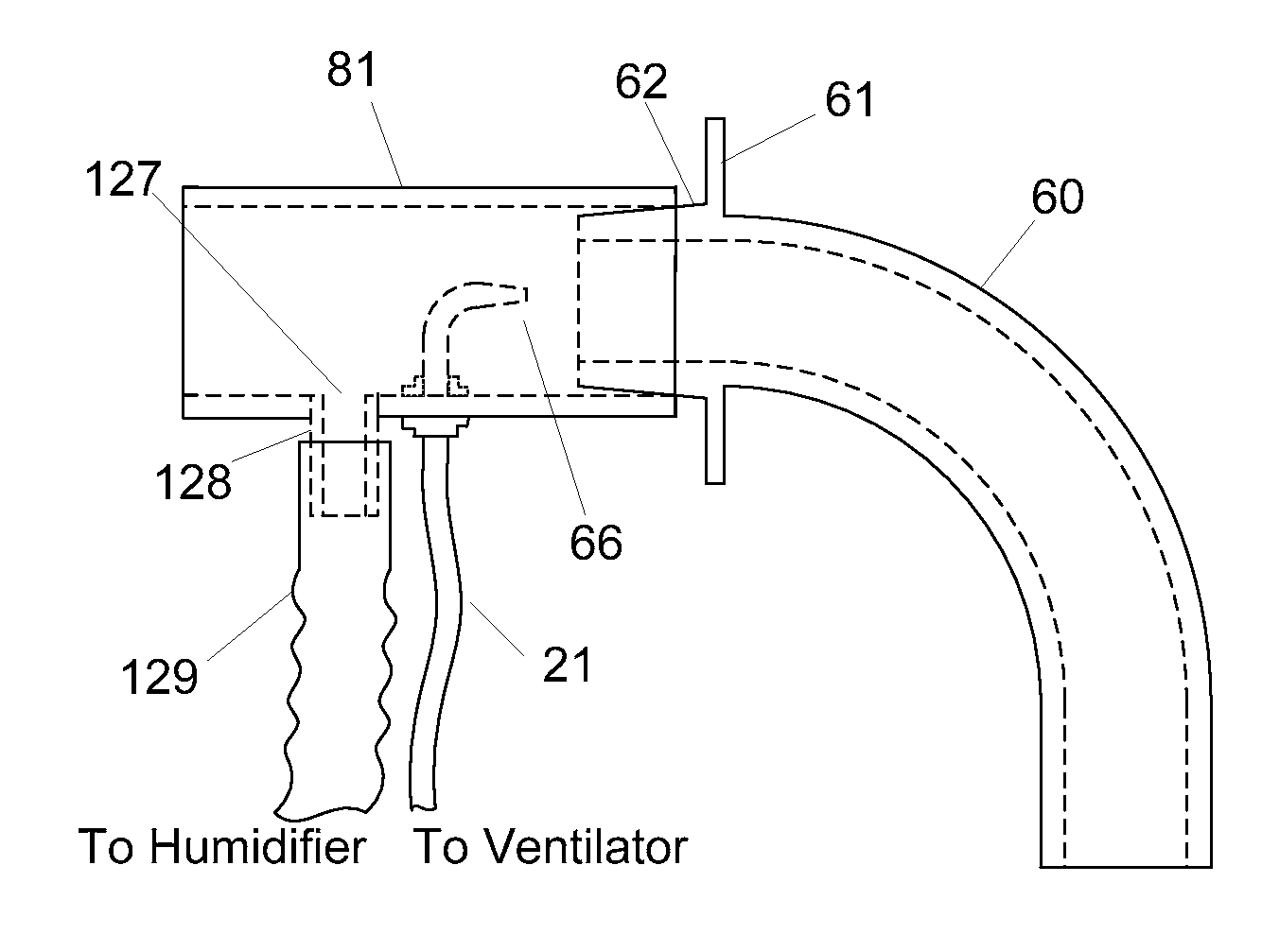
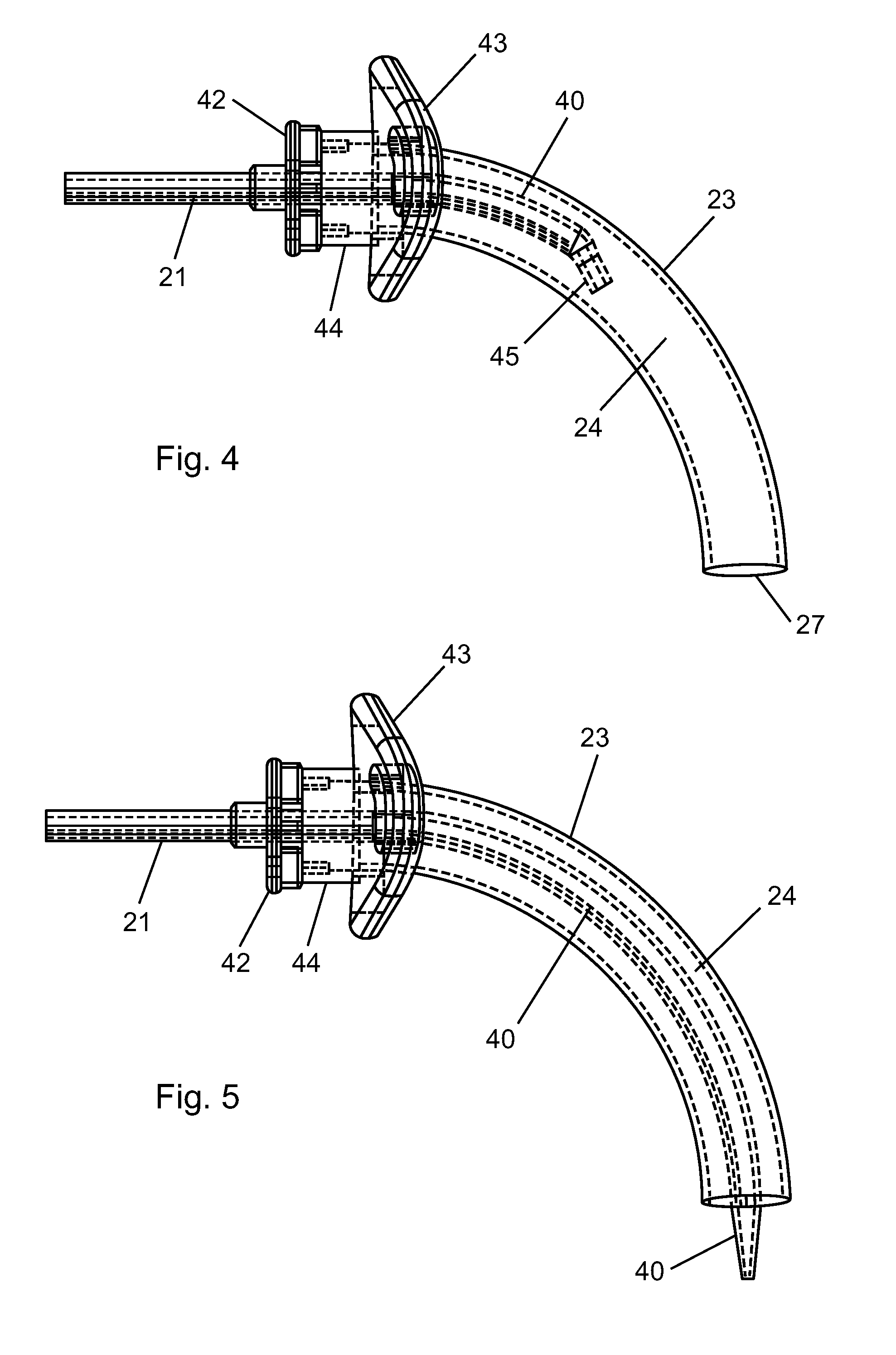
[0059]In some cases, special airflow delivery fluid dynamics can be created by special drive pressures and escape velocities of the ventilation gas, and in other cases the special airflow delivery fluid dynamics can be created by special patient interface configurations. Embodiments of the present invention may include special patient interface configurations and geometries that optimize the efficacy of open system augmented ventilation.

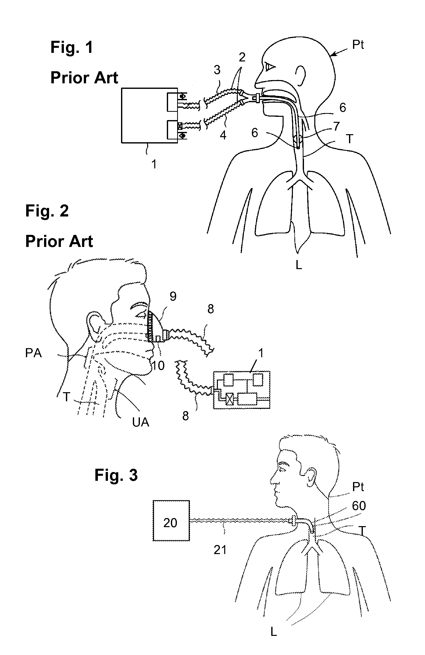
[0060]FIG. 1 describes a conventional ventilation system, known as controlled mechanical ventilation (CMV) in which a ventilator 1 is connected to a patient Pt with a dual limb gas delivery circuit 2 and delivers gas to the patient Pt via an inspiratory limb 3 and gas is exhaled from lungs L back to the ventilator 1 through an expiratory limb 4. A typical patient ventilation interface is an endotracheal tube 6 with a cuff 7 within a trachea T such that the patient's lung L is closed off from ambient air, and is only connected to an air source through...


PUM


Abstract

Methods, systems and devices are described for providing mechanical ventilation support of a patient using an open airway patient interface. The system includes gas delivery circuit and patient interface configurations to optimize performance and efficiency of the ventilation system. A ventilation system may include a ventilator for supplying ventilation gas. A patient interface may include distal end in communication with a patient airway, a proximal end in communication with ambient air, and an airflow channel between the distal end and the proximal end. A gas delivery circuit may be adapted to attach to the patient interface without occluding the patient interface to allow ambient air to flow from outside the patient interface to the patient airway. The ventilation gas may entrain air from ambient and from the patient airway.

Description

PRIORITY APPLICATIONS[0001]This application claims priority to U.S. Provisional Patent Application Ser. No. 61 / 091,198, filed Aug. 22, 2008 and U.S. Provisional Patent Application Ser. No. 61 / 136,269, filed Aug. 22, 2008; the disclosures of which are hereby incorporated by reference in their entireties.CROSS-REFERENCE TO RELATED APPLICATIONS[0002]This application further incorporates by reference in their entireties: U.S. Non-Provisional patent application Ser. No. 10 / 771,803 (U.S. Printed Publication 2005 / 0034721), filed Feb. 4, 2004, U.S. Non-Provisional patent application Ser. No. 10 / 870,849 (U.S. Printed Publication 2005 / 0005936), filed Jun. 17, 2004, and U.S. Non-Provisional patent application Ser. No. 12 / 239,723 (U.S. Printed Publication 2009 / 0151724), filed Sep. 26, 2008.FIELD OF THE INVENTION[0003]The present invention relates to ventilation therapy for persons suffering from respiratory impairment and breathing disorders, such as chronic obstructive pulmonary disease (COPD)...

Claims


Application Information

Patent Timeline
IPC IPC(8): A61M16/00A61M16/06A61M16/20A61M16/16
CPCA61M16/04A61M16/201A61M16/0465A61M16/06A61M16/0816A61M16/1045A61M16/12A61M16/16A61M16/20A61M16/208A61M2016/0027A61M2016/003A61M2016/1025A61M2016/103A61M2202/0208A61M2205/3368A61M2230/205A61M2230/432A61M2230/435A61M2230/65A61M16/0468A61M16/0833A61M16/085A61M16/0858A61M16/101A61M16/125A61M16/0434A61M16/0825A61M16/205A61M2202/03A61M16/127A61M2202/0007
Inventor ALLUM, TODDWONDKA, ANTHONY D.CIPOLLONE, JOSEPH
Owner BREATHE TECHNOLOGIES INC
Learn More