LED driving circuit

a driving circuit and led technology, applied in the direction of lighting apparatus, electroluminescent light sources, light sources, etc., can solve the problems of stray capacitance, stray inductance and stray capacitance, and the high speed switching control of turning on and off led devices with narrow width current pulses, for example, units of 10 ns,

Inactive Publication Date: 2010-03-25
KOA CORP
View PDF20 Cites 41 Cited by
  • Summary
  • Abstract
  • Description
  • Claims
  • Application Information

AI Technical Summary

Benefits of technology

[0007]The present invention has been made in view of the above problems. It is first object of the present invention to provide an economical LED driving circuit, which can drive many serially connected LED devices by using relatively low withstanding voltage switching device, even if the number of serially connected LED devices increases.
[0008]Also, it is second object of the present invention to provide an LED driving circuit, which can adjust electrical current range from small current range to large current range, and in which fine adjustment of the electrical current can be possible, so as to change LED light volume widely and accurately.
[0009]Further, it is third object of the present invention to provide an LED driving circuit, in which high-speed control of turning on and off the LED devices can be possible with using narrow width current pulse, for example, units of 10 nS, and precisely controlled current can be supplied for flowing through the serially connected LED circuit.
[0011]According to the LED driving circuit of the present invention, when the switching device is turned off, a minute current flows through the circuit device, which is connected in parallel with the switching device, to the extent that the LED devices are not turned on. Accordingly, a voltage drop is generated along serially connected LED devices, and applied voltage to the switching device is reduced by the voltage drop. Therefore, a switching device with low applicable maximum voltage VCEO can be adopted, and it makes possible to produce an economical LED driving circuit, which can drive many serially connected LED devices by using relatively low withstanding voltage switching device.
[0013]According to the LED driving circuit of the present invention, by providing with a plural of resistors connected in parallel with each other, and second switching devices, each of which is serially connected with each of the plural of resistors, and a setting circuit for setting on or off of the second switching devices respectively, a synthetic resistance between the first switching device connected with the serially connected LED circuit and the ground terminal can be changed widely. Therefore, current ranges of the electrical current flowing through the serially connected LED circuit can be adjusted widely from small current to large current. And, by connecting an output terminal of a D / A converter with one input terminal of the multiplexer, and supplying a variable voltage from the D / A converter to the control terminal (base terminal) of the first switching device when LED devices are turned on, fine adjustment of an electrical current flowing through the serially connected LED circuit can be possible. Further, by connecting a ground voltage with the other input terminal of the multiplexer, and supplying GND voltage to the control terminal of the first switching device, an electrical current flowing through the serially connected LED circuit can be shut off immediately.
[0015]According to the LED driving circuit of the present invention, it makes high-accuracy and wide-range on and off of current pulses, which are supplied to the serially connected LED circuit, possible by using high-speed multiplexer and wide frequency band buffer amplifier, by switching LED on signal and off signal with a lighting time control circuit, and by providing with a switching device cascade connected with the first switching device.

Problems solved by technology

Further, upon the lighting equipment and so on, there is a problem that wiring length tends to be longer since many LED devices are series-parallel connected, stray inductance and stray capacitance tends to be large, and high speed switching control of turning on and off the LED devices with narrow width current pulse, for example, units of 10 nS, tends to be difficult.

Method used


Image

  • LED driving circuit
  • LED driving circuit
  • LED driving circuit

Examples


first embodiment

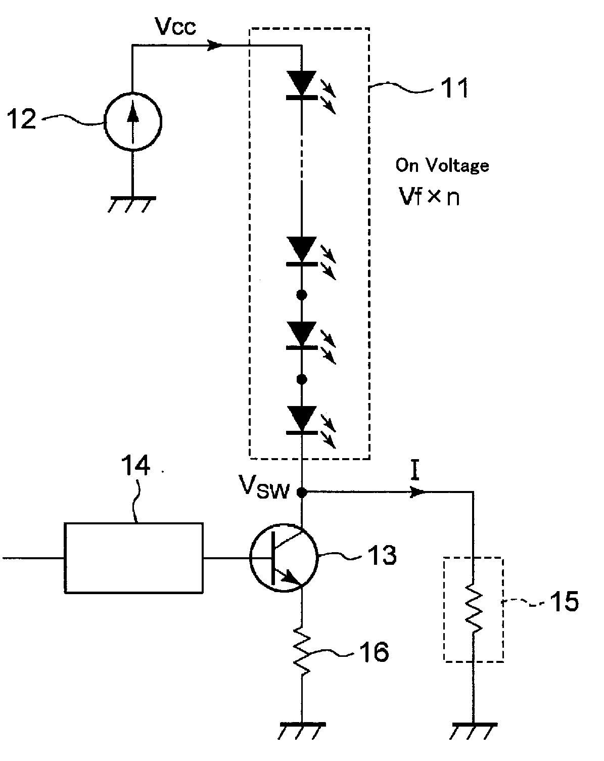
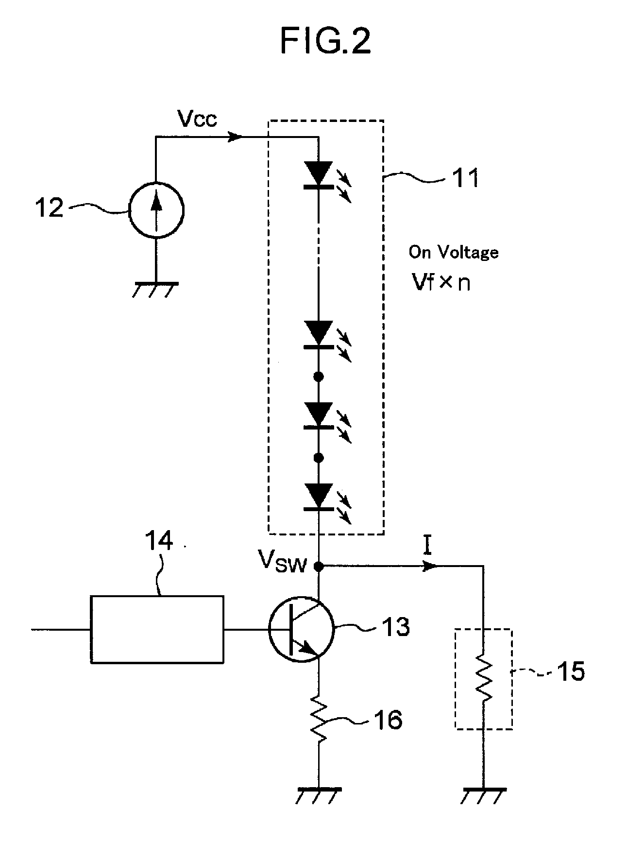
[0031]Thus, the LED driving circuit of the present invention can reduce the voltage, which is applied to the switching device 13 when the switching device 13 is off, and it can make possible to use relatively low withstanding voltage switching device. That is, to produce an economical LED driving circuit, in which, even if number (n) of serially connected LED devices increases, and relating to this, the power supply voltage Vcc increases over than applicable maximum voltage Vceo of the switching device, the voltage applied to the switching device can be reduced, and the switching device can be prevented from damaged and destroyed.

[0032]FIG. 2 is a circuit diagram showing an LED driving circuit according to a first embodiment of the present invention, and FIG. 3 is a circuit diagram showing an example of an LED array, which is an object driven by the LED driving circuit.

[0033]The LED driving circuit shown in FIG. 2 supplies an electrical current to flow through the LED array 11 shown...

second embodiment

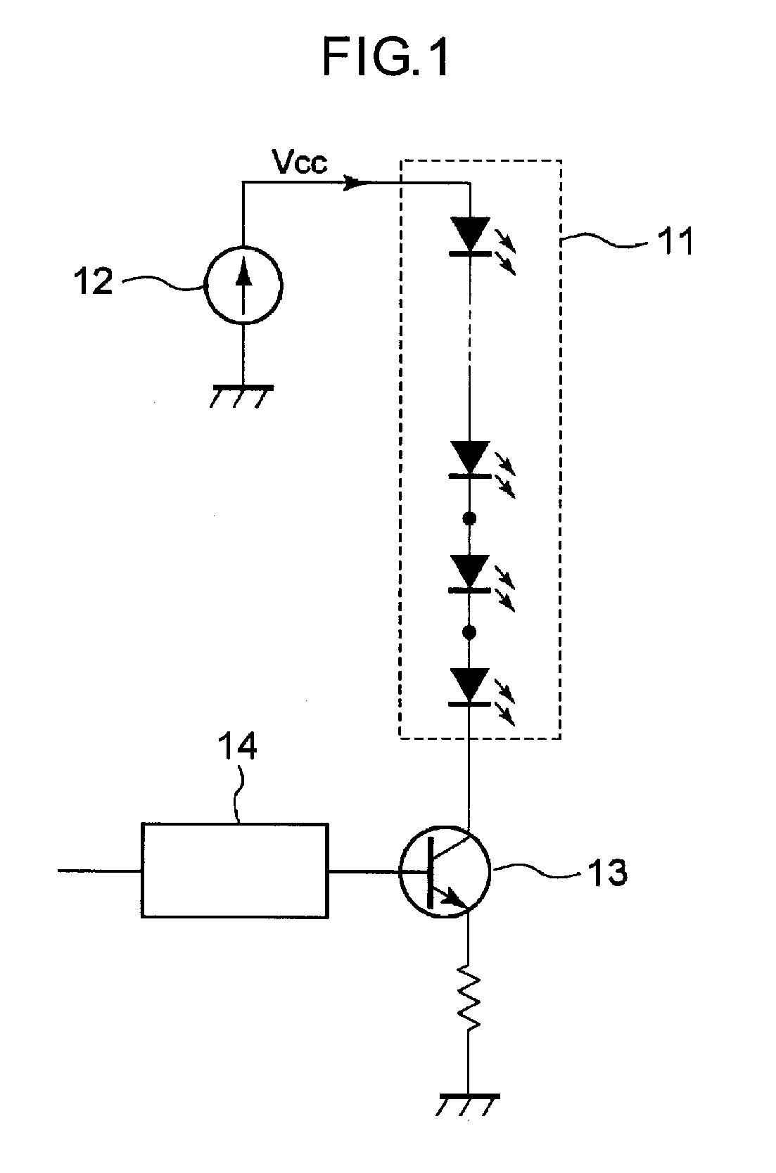
[0047]Next, the LED driving circuit according to the present invention will be described below. The conventional LED driving circuit, which is shown in FIG. 1, supplies a constant voltage to the base terminal of the switching device 13, and when the transistor becomes on, almost constant current flows through the transistor, wherein the constant current is determined by a DC power supply 12, a serially connected LED circuit 11, and a current setting resistor 16 (constant current circuit). Therefore, it is difficult to control brightness of the panel widely, for example, from dim state to full lighting state.

[0048]Thus, the purpose of the second LED driving circuit of the present invention is to provide an LED driving circuit, which can control electrical current range widely from small current to large current, and which also can control fine adjustment of the electrical current.

[0049]FIG. 7 shows a second embodiment of the LED driving circuit according to the present invention. The...

third embodiment

[0086]Next, third embodiment of the LED driving circuit of the present invention will be described.

[0087]According to conventional LED driving circuit shown in FIG. 1, there is a problem that it is difficult to control high speed lighting and lighting-out by using narrow width current pulse, such as units of 10 nS, since many LED devices are serially connected and wiring length becomes so long, and stray inductance and stray capacitance are so large.

[0088]Therefore, it is an object of this embodiment to provide an LED driving circuit, which can control high speed lighting and lighting-out by using narrow width current pulse, such as units of 10 nS, and can supply high accuracy current flowing through the serially connected LED circuit. FIG. 10 shows a structural example of the LED driving circuit according to third embodiment of the present invention.

[0089]The LED driving circuit comprises a DC power supply 12; a serially connected LED circuit 11 in which many LED devices are serial...


PUM


Abstract

An LED driving circuit is provided for making it possible to economically drive a serially connected LED circuit by means of a switching device with a relatively low withstanding voltage even if the number of serially connected LED devices increases. In an LED driving circuit provided with a serially connected LED circuit (11) in which many LED devices are serially connected and a switching device (13) serially connected with the serially connected LED circuit (11) to control that an electrical current flowing through the serially connected LED circuit (11) is turned on or off, wherein a circuit device (15), which comprises a resistor, a constant voltage diode, a constant current diode, or the like, is connected in parallel with the switching device to make a minute current flow through the serially connected LED circuit (11) to the extent that the LED devices are not turned on when the switching device is turned off.

Description

TECHNICAL FIELD[0001]The present invention relates to an LED driving circuit, which controls an electrical current flowing through a serially connected LED circuit, in which many LED devices are serially connected, and which turns on and off the many LED devices with all together.BACKGROUND ART[0002]Heretofore, upon a lighting equipment and so on, there has been used that a plurality of serially connected LED circuits, in which many LED devices are serially connected, is connected in parallel, and an electrical current flowing through the plurality of serially connected LED circuits is turned on and off by using a switching device (transistor) so as to control turning on and off the many LED devices with all together (see, for example, Japanese laid-open patent publication No. 2001-15278, No. 2003-100472, No. 2003-139712, No. 2005-50704).[0003]FIG. 1 is a view showing a conventional general structure of such an LED driving circuit. A serially connected LED circuit 11 is formed by co...

Claims


Application Information

Patent Timeline
Patent Type & Authority Applications(United States)
IPC IPC(8): H05B37/02
CPCH05B33/0845H05B33/0818H05B45/10H05B45/392H05B45/345
Inventor OHASHI, MITSUOSAGARA, IWAOKOMATSU, HIDEYUKI
Owner KOA CORP
Why Eureka
Try Eureka