Mask inspection apparatus, and exposure method and mask inspection method using the same

a mask and mask technology, applied in the field of mask inspection apparatus, can solve the problems of time taken, difficult to detect the positional displacement amount with satisfactory accuracy, and the line width of each chrome pattern becomes thicker than the design valu

Inactive Publication Date: 2010-03-25
NUFLARE TECH INC
View PDF9 Cites 19 Cited by
  • Summary
  • Abstract
  • Description
  • Claims
  • Application Information

AI Technical Summary

Benefits of technology

[0025]According to another aspect of the present invention, in an exposure method, positional displacement amounts between optical images of a mask and reference images obtained from design data of the mask is acquired by the mask inspection apparatus according

Problems solved by technology

The method adopted in the line 301 is however accompanied by a problem that since there is a need to perform the temporary exposure, the time is taken until mass production is started by the wafer exposure apparatus 305 using the mask having passed the defect inspection of the mask inspection apparatus 304.
Since the measurement of the positional displacement amount of each resist pattern formed by the temporary exposure is affected by the roughness of the re

Method used


Image

  • Mask inspection apparatus, and exposure method and mask inspection method using the same
  • Mask inspection apparatus, and exposure method and mask inspection method using the same
  • Mask inspection apparatus, and exposure method and mask inspection method using the same

Examples


first embodiment

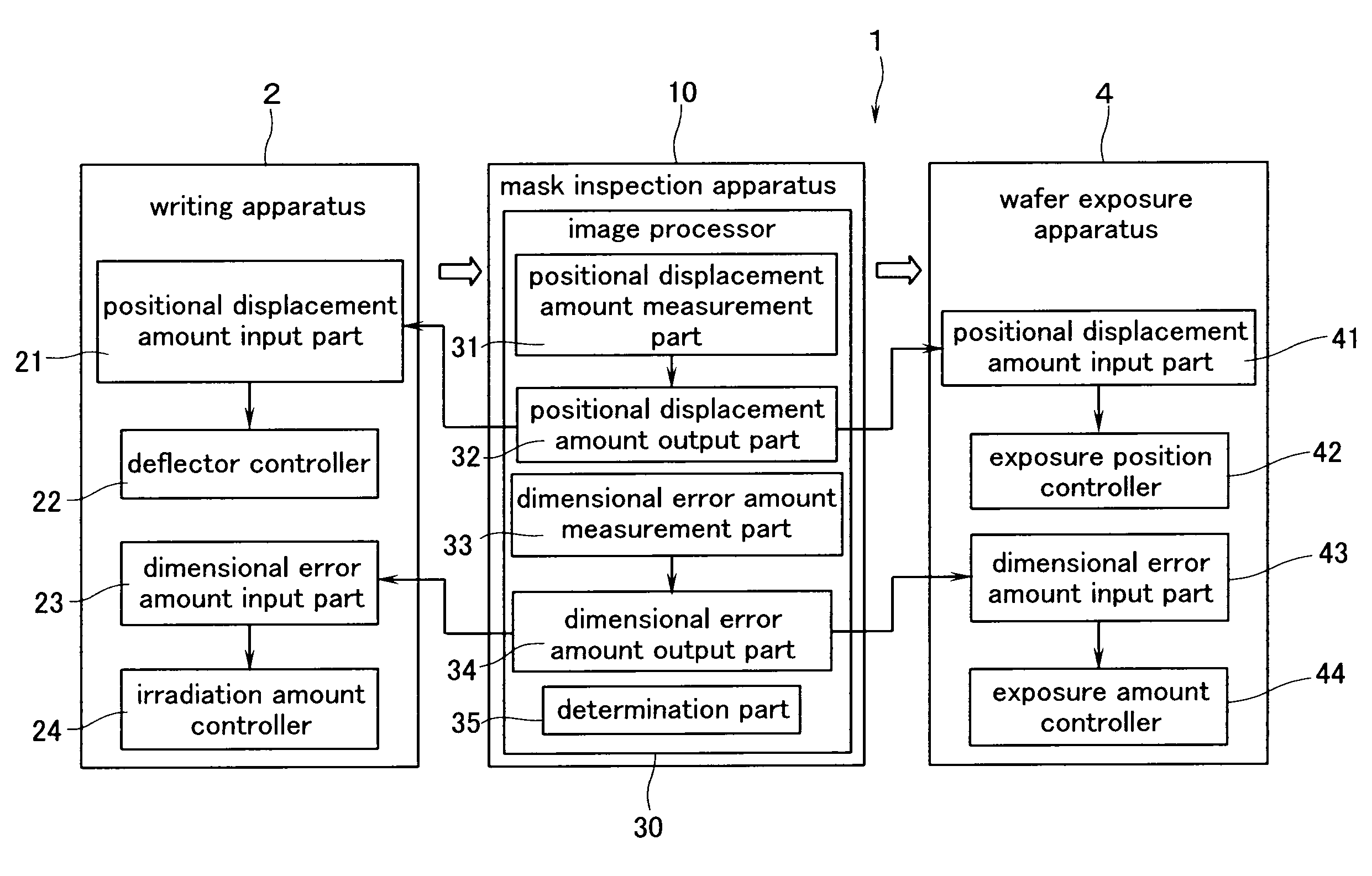
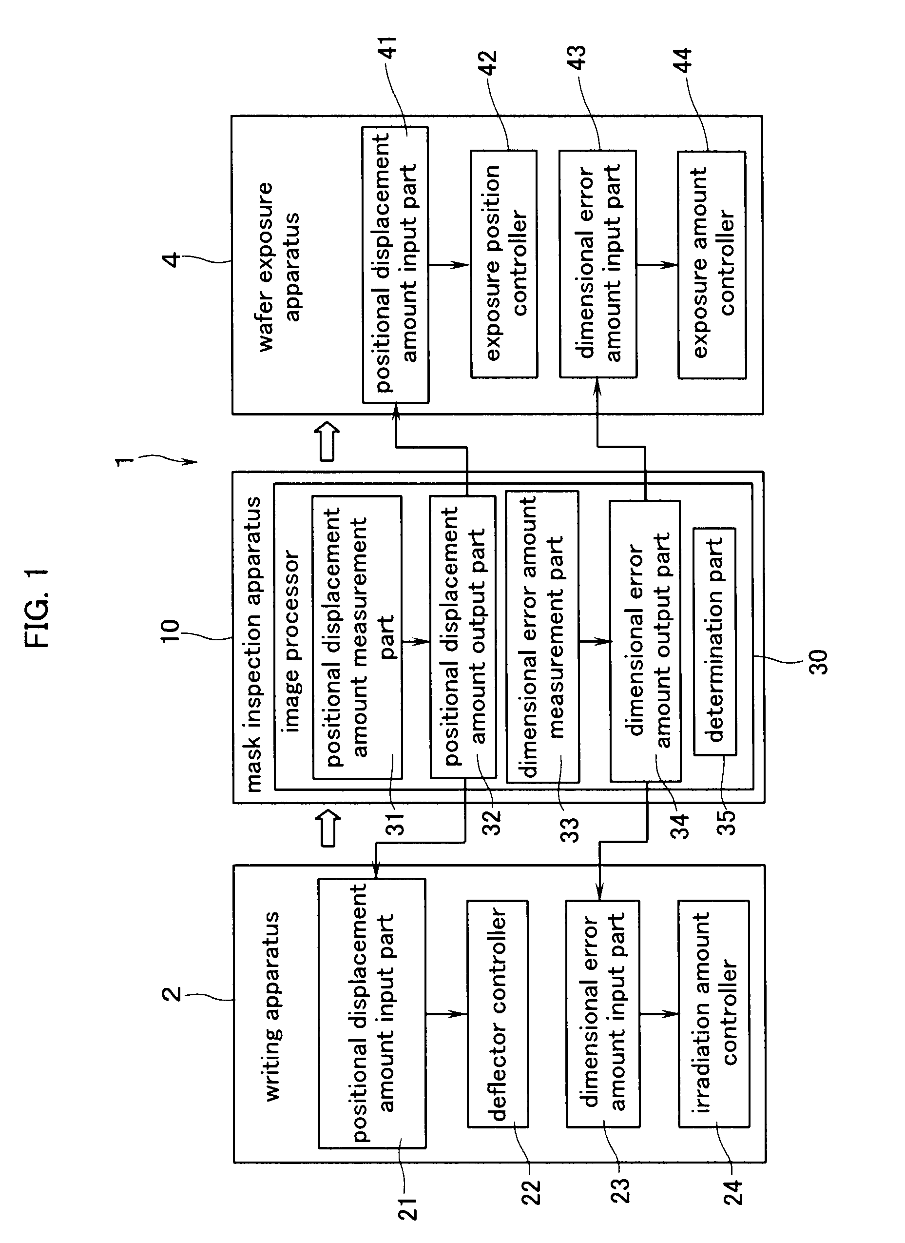
[0045]FIG. 1 is a diagram showing a configuration of a mask-related production line in the present invention. The mask line 1 shown in FIG. 1 is equipped with a writing apparatus (Charged particle beam writing apparatus like an electron beam writing apparatus, for example) 2, a mask inspection apparatus 10 and a wafer exposure apparatus 4 using a reduction or scale-down projection technology.

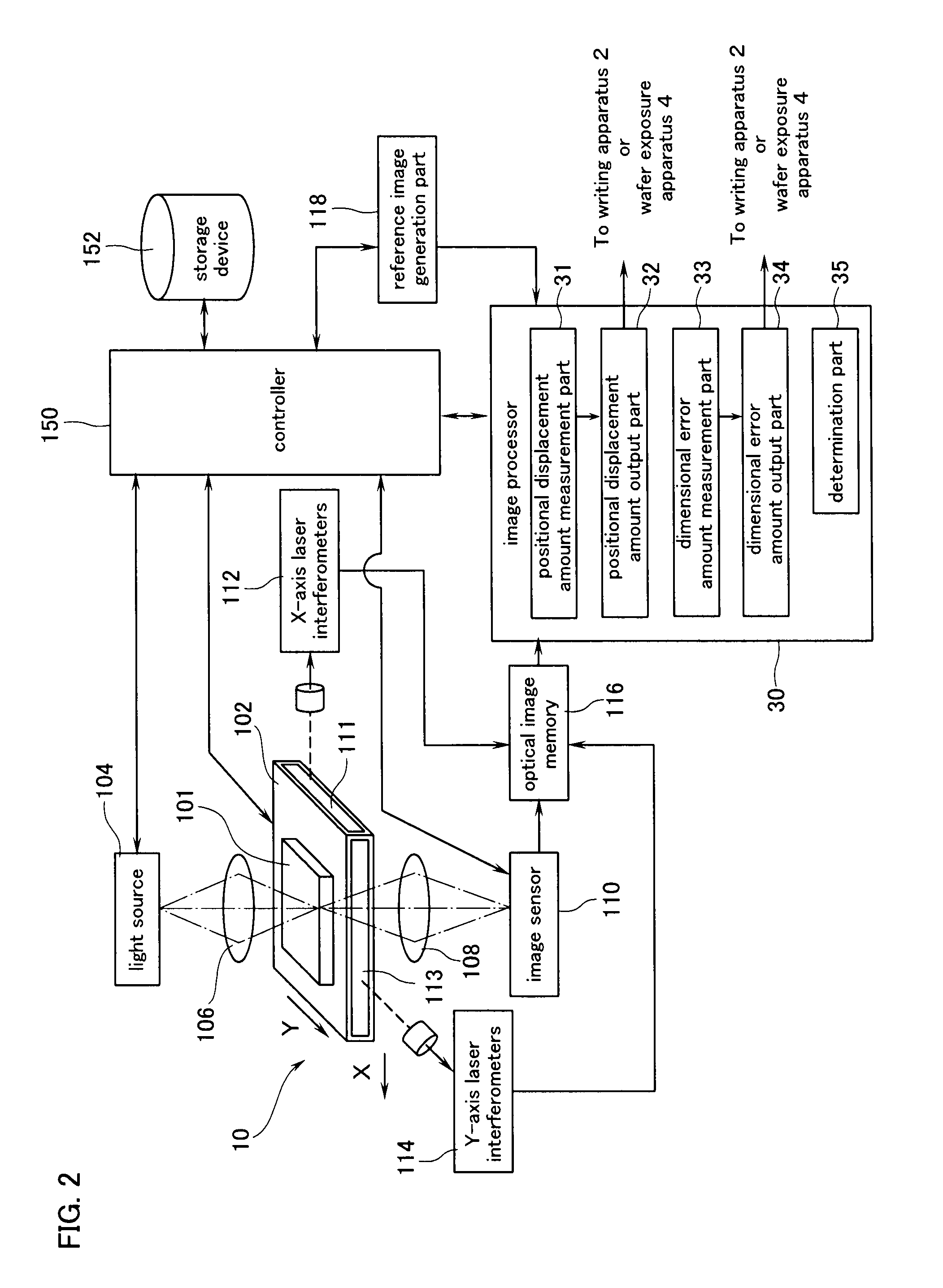
[0046]The mask inspection apparatus 10 is equipped with an image processor 30. The image processor 30 includes a positional displacement amount measurement part 31, a positional displacement amount output part 32, a dimensional error amount measurement part 33, a dimensional error amount output part 34 and a determination part 35. Other detailed configurations of the mask inspection apparatus 10 will be explained later.

[0047]The positional displacement amount measurement part 31 measures the amounts of positional displacements of an optical image of a mask to be inspected and a reference image c...

second embodiment

[0088]A second embodiment in which the present invention is applied to a mask for double patterning will next be explained.

[0089]FIG. 6 is a conceptual diagram showing a configuration of a mask inspection apparatus 100 according to the second embodiment of the present invention. The mask inspection apparatus 100 is different from the mask inspection apparatus 10 shown in FIG. 2 in that it is equipped with an image processor 120 instead of the image processor 30. Since the mask inspection apparatus 100 is similar in other configuration to the mask inspection apparatus 10, the detailed description thereof is omitted.

[0090]A first mask 101A used in double patterning is placed on a stage 102. Optical images in the entire inspected area or region R of the mask 101A are stored in an optical image memory 116. Thereafter, the mask 101A is replaced with a second mask 101B used in double patterning. Optical images in the entire inspected region R of the mask 101B are stored in the optical ima...


PUM


Abstract

The present invention provides a mask inspection apparatus and method capable of inspecting masks used in double patterning with satisfactory accuracy.
Optical images of two masks are acquired (S100). The acquired optical images of the two masks are combined together (S102). Relative positional displacement amounts of patterns of the first mask and patterns of the second mask are measured at the combined image (S104). The measured relative positional displacement amounts are compared with standard values to thereby determine whether the two masks are good (S106).

Description

BACKGROUND OF THE INVENTION[0001]1. Field of the Invention[0002]The present invention relates to a mask inspection apparatus for inspecting a defect of a mask, and an exposure method and a mask inspection method which use the mask inspection apparatus.[0003]2. Background Art[0004]A reticle or photomask (hereinafter called “mask”) is used in a manufacturing process of a semiconductor device to form each pattern on a substrate. If a mask is defective, a defect is transferred onto a pattern. To avoid such undesirable transfer, a mask defect inspection is generally carried out with the use of an inspection apparatus.[0005]A Die-to-Die inspection and a Die-to-Database inspection are known in the art as mask inspection methods.[0006]In the Die-to-Die inspection, optical images of the same pattern written at different positions of one mask are compared with each other. On the other hand, in the Die-to-Database inspection, a reference image generated from design data (CAD data) used upon ma...

Claims


Application Information

Patent Timeline
IPC IPC(8): G06K9/00G01B11/00G01B11/02G01N21/956G03F1/84H01L21/027
CPCB82Y10/00B82Y40/00G01N21/95607H01J37/3174G03F1/84G03F7/70525G03F7/70991G01N2021/95676
Inventor TAMAMUSHI, SHUICHITAKAMATSU, NORIYUKINOMURA, TAKEHIKOIIRI, MASAHIRO
Owner NUFLARE TECH INC
Why Eureka
Try Eureka