

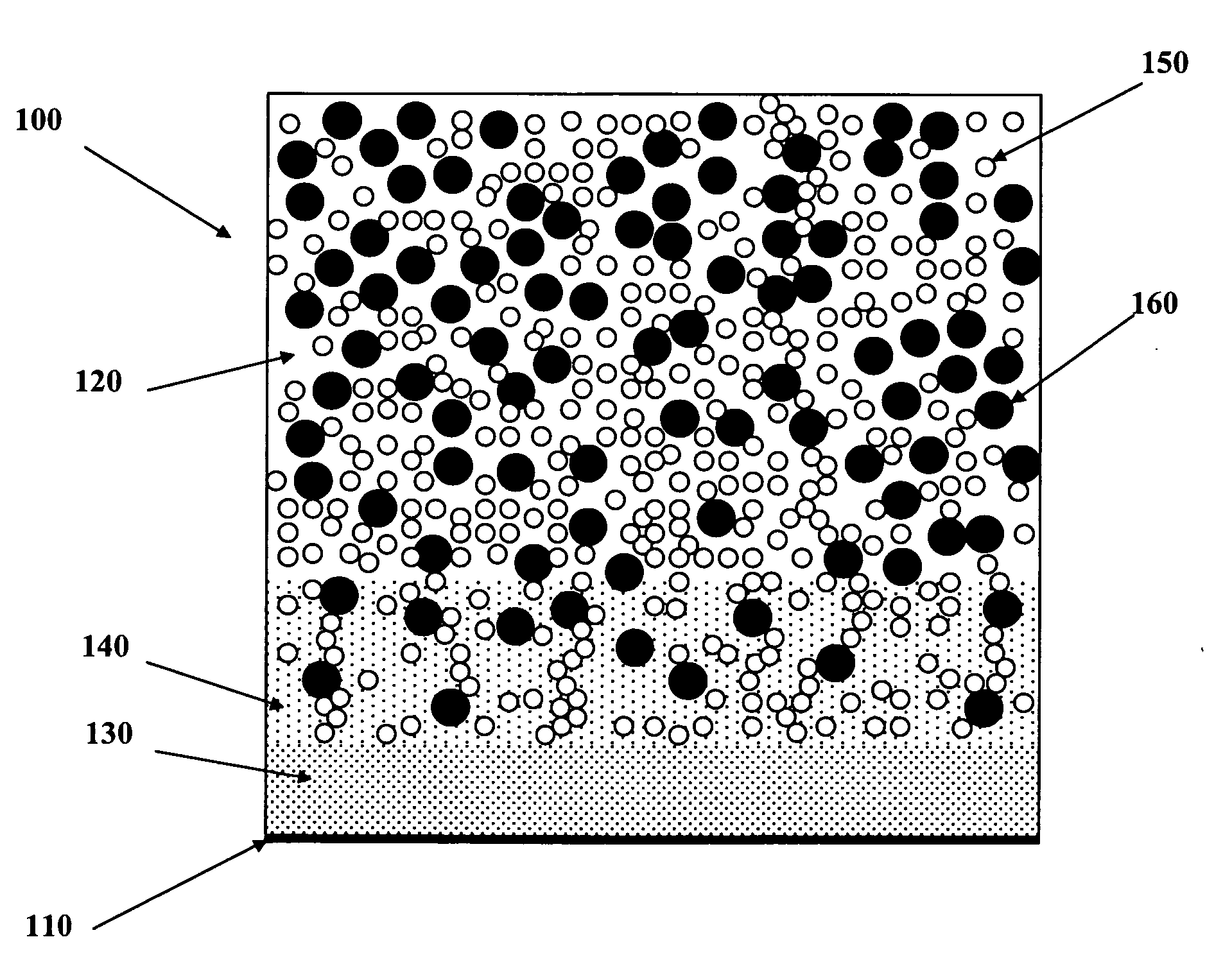
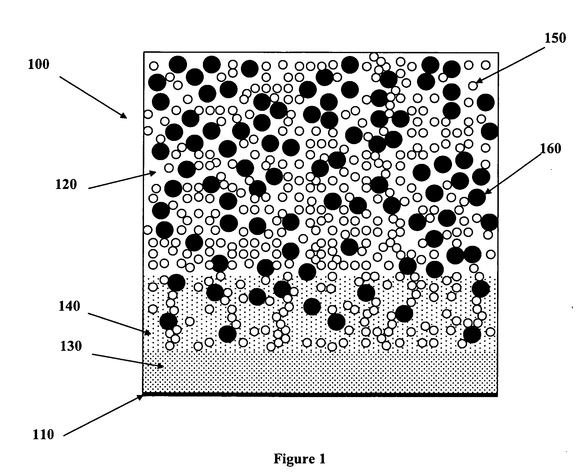
Nanocomposite electrodes and related devices
a technology of nanocomposite electrodes and electrodes, applied in the field of nanocomposite electrodes, can solve the problems of nanoscale electrodes that cannot be pressed into the current collector to form mechanical interlocking, nanoscale electrodes that cannot be made with nanoscale materials, and new manufacturing challenges
- Summary
- Abstract
- Description
- Claims
- Application Information
AI Technical Summary
Problems solved by technology
Method used
Image

Examples
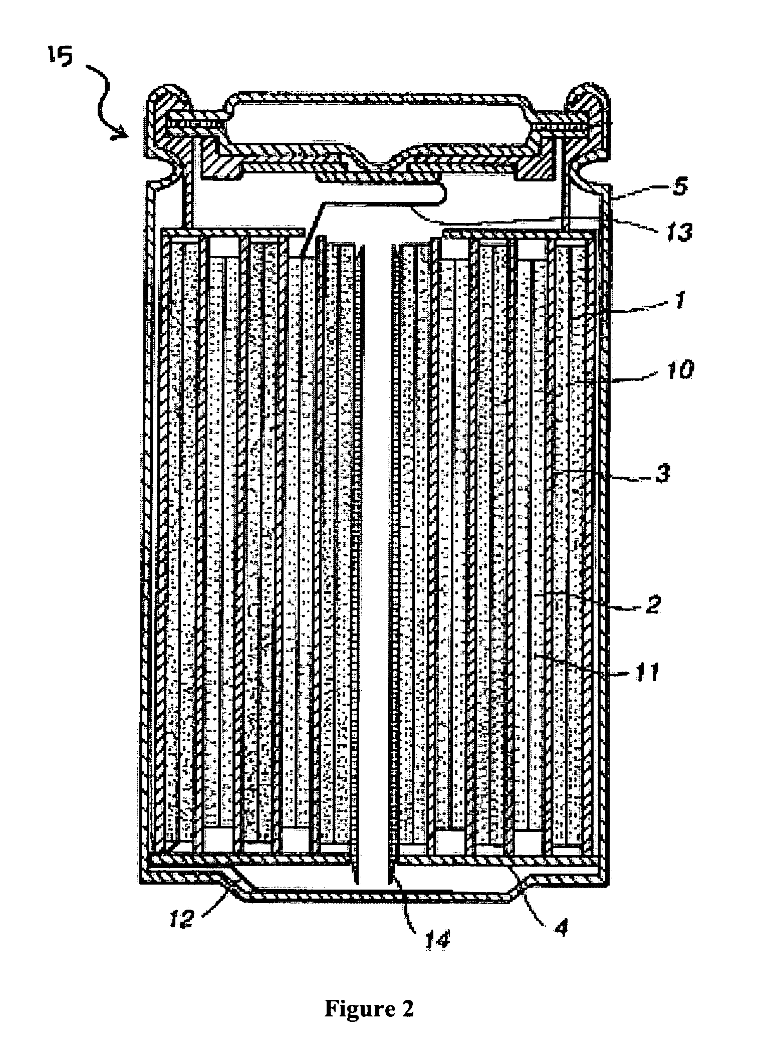
example 1
[0077]A sample of positive electrode current collector (Al foil) was coated on both sides with a composition of Electrodag 112 (Acheson, a National Starch and Chemical Company) (including carbon black, graphite, 2-butoxy-ethanol, water, and acrylic acid-isobutyl acrylate styrene polymer). After application to the current collector, the coating was allowed to dry for several minutes at an elevated temperature of 120° C. The coated current collector was then immersed for 1 min. with mild stirring movement in N-methylpyrrolidinone (NMP) solvent (Aldrich, Reagent Grade). Upon exposure to the NMP, the coating softened and a majority could easily be wiped clean from the current collector using a cotton swab dipped in the same NMP solution, revealing a clean metallic surface of aluminum foil.
[0078]In a second experiment, a coated current collector was prepared as described above. A cotton swab saturated with NMP solution was wiped across the surface of the coated collector. As before, a ma...
example 2
[0079]Standard battery grade aluminum foil with a thickness of 15 micron was prepared for electrode coating. An approximately 3 μm thick precoating of Electrodag 112 was applied to the foil, using micro gravure coating, and a loading of 0.7 g / m2. The precoating coverage was approximately of 50%.
[0080]An electrode slurry in NMP was prepared from the following materials: 90% LiFePO4 (nanoscale, as described herein) with a surface area of 30 m2 / g; 5% carbon black; and 5% PVDF at a solids loading of 40% (all percentages are weight percentages).
[0081]The electrode slurry was coated onto the precoated foil (above) using a dr blade at a LiFePO4 loading of 12 mg / cm2 and allowed to dry in a 100° C. oven. For comparison, the electrode slurry was also coated onto battery grade aluminum foil that had not been precoated, also at a LiFePO4 loading of 12 mg / cm2 and allowed to dry in a 100° C. oven.
[0082]Each coated electrode was pressed to a thickness of 100 μm and bent around a 4 mm diameter mand...
PUM
| Property | Measurement | Unit |
|---|---|---|
| thickness | aaaaa | aaaaa |
| thickness | aaaaa | aaaaa |
| thickness | aaaaa | aaaaa |
Abstract
Description
Claims
Application Information