Combustion system with steam or water injection

a combustion system and water injection technology, applied in the field of combustion systems, can solve the problems of insufficient flow rate, reducing the purity of co2 /sub>2 in the flue gas, and the original heat transfer profile of the air fired or air/coal boiler is not adequately matched by fgr, so as to reduce or eliminate the amount of rfg, reduce or eliminate the amount of conventional fgr, and achieve higher co2 purities

Inactive Publication Date: 2010-04-01
AIR PROD & CHEM INC
View PDF18 Cites 29 Cited by
  • Summary
  • Abstract
  • Description
  • Claims
  • Application Information

AI Technical Summary

Benefits of technology

[0010]An advantage of the present disclosure is reducing or eliminating the conventional FGR for an oxy / fuel combustion boiler. By reducing or eliminating the amount of RFG, detrimental impurities such as SO2 and SO3 can be reduced or eliminated within the system permitting the use of conventional materials of construction to be used for the system surface areas.
[0011]Another advantage of the present disclosure is higher CO2 purities in the flue gas are provided, which improves the efficiency of the CO2 purification and compression system.
[0012]Yet another advantage of the present disclosure is that the water can be supplied at higher pressures than the conventional RFG (˜1-5 psig) which further reduces the transport medium sizing.
[0013]Still yet another advantage of the present disclosure is that multiple injections of steam or preheated boiler feed water or water into the boiler and / or convective section may 1) desirably permit the control of the relative radiant and convective heat transfer and / or 2) desirably increase the overall mass flow through the convective section.
[0014]A further advantage of the present disclosure is better matching the original heat transfer profile of a conventional air fired boiler. For example, the mass flow rate within the boiler can be controlled to match the original air fired boiler flow rates or allow a more optimum mass flow profile within the boiler.
[0015]Another advantage of the present disclosure is desirably permitting additional control of the relative radiant and convective heat transfer.

Problems solved by technology

However, recycled flue gas (“RFG”) can introduce impurities into the flue gas.
In addition, the original heat transfer profile of the air fired or air / coal boiler is not adequately matched by FGR.
However, FGR reduces the purity of the CO2 in the flue gas via recycling and / or building up impurities in the flue gas.
In the known system, air ingress is more detrimental to a CO2 capture power plant than an air fired (i.e. air / fuel or air / coal combustion) power plant because the external air reduces the purity of the CO2.
Known methods of injecting water into a boiler system are not continuous and do not permit large enough flow rates.
For example, soot blowers are currently used to inject N2, water (liquid water or steam), or air to remove soot, slag, and / or ash deposits, but these systems are used for a short period of time to remove the particular deposits and not continuously because of the effect on plant efficiency.

Method used


Image

  • Combustion system with steam or water injection
  • Combustion system with steam or water injection
  • Combustion system with steam or water injection

Examples


example

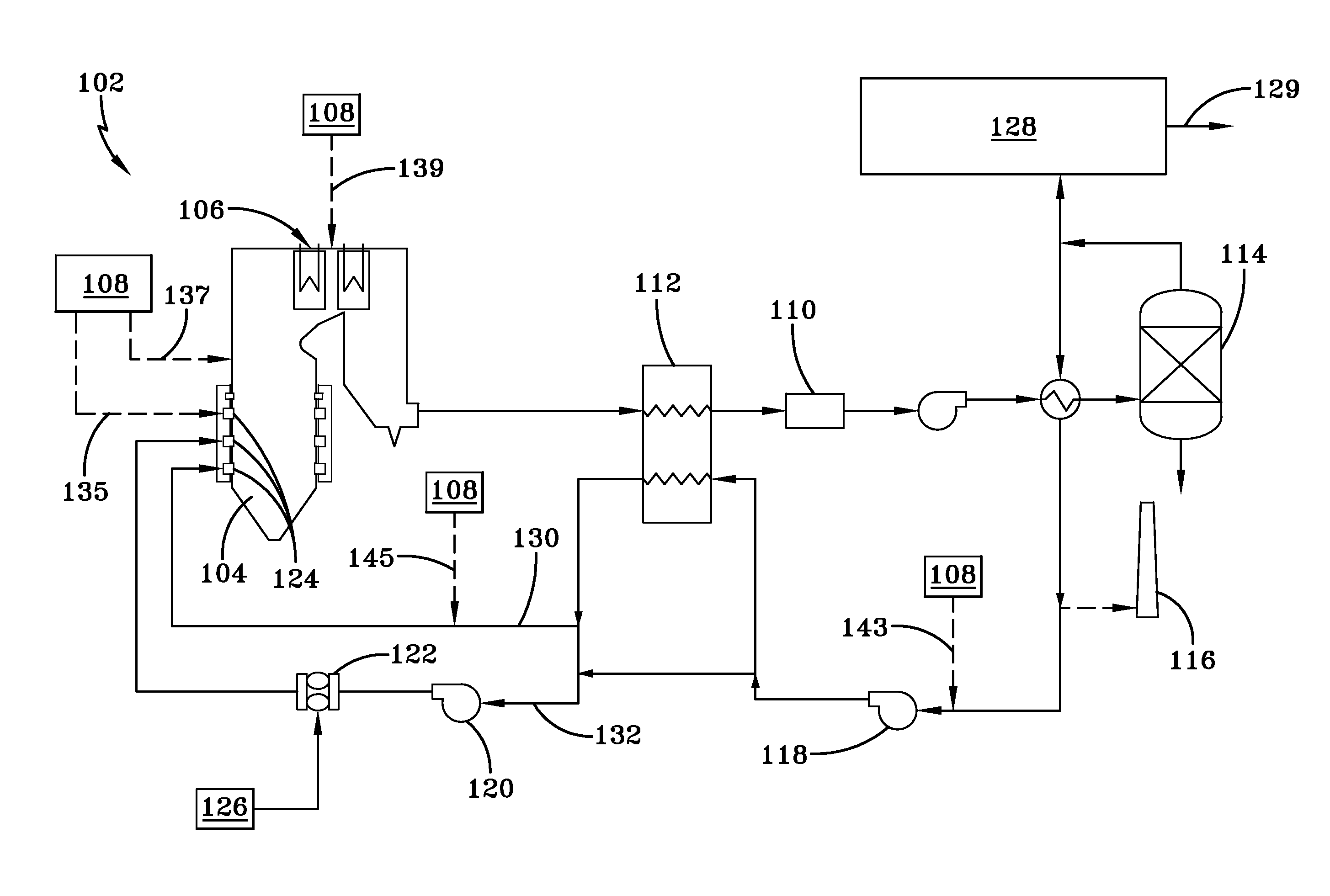
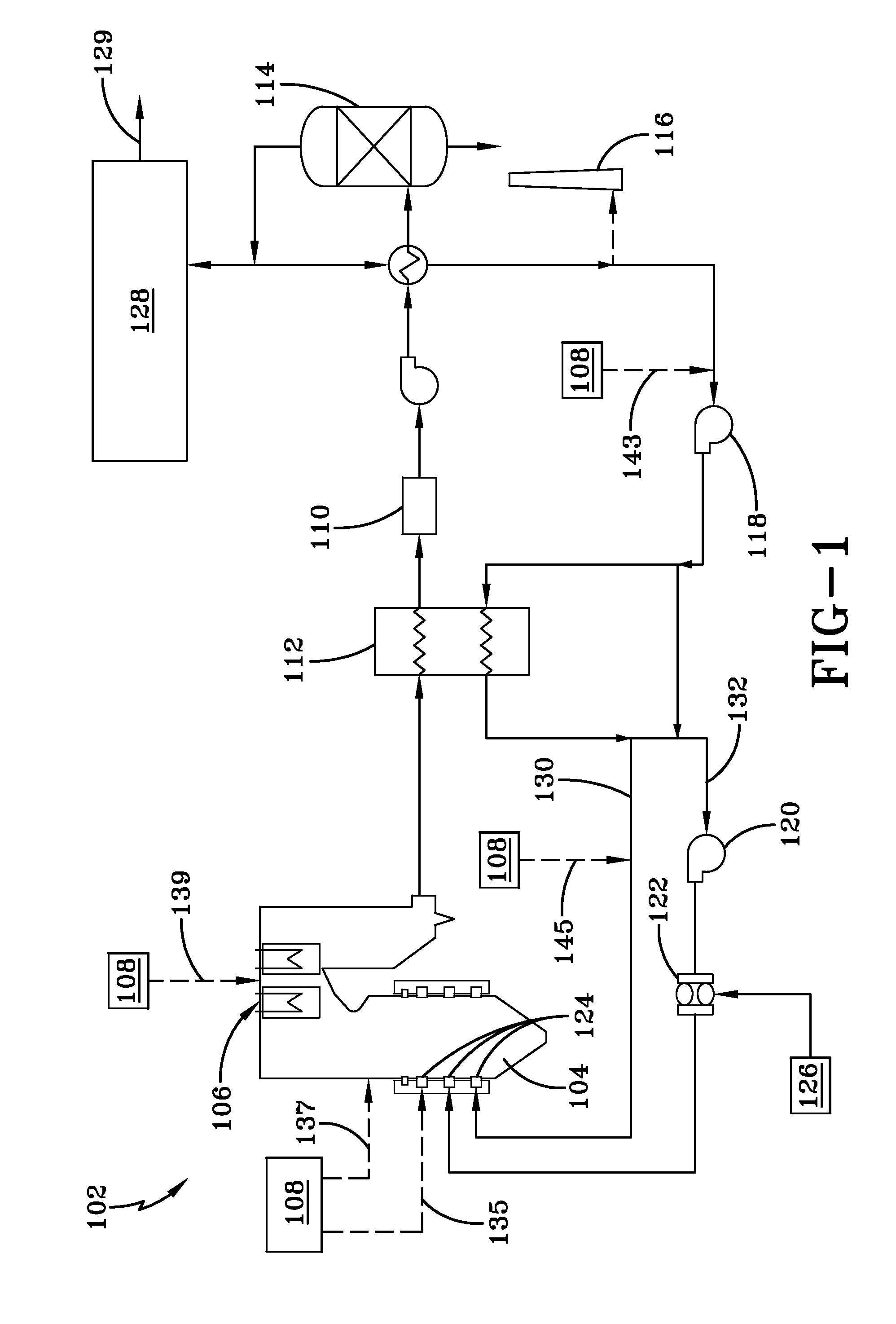
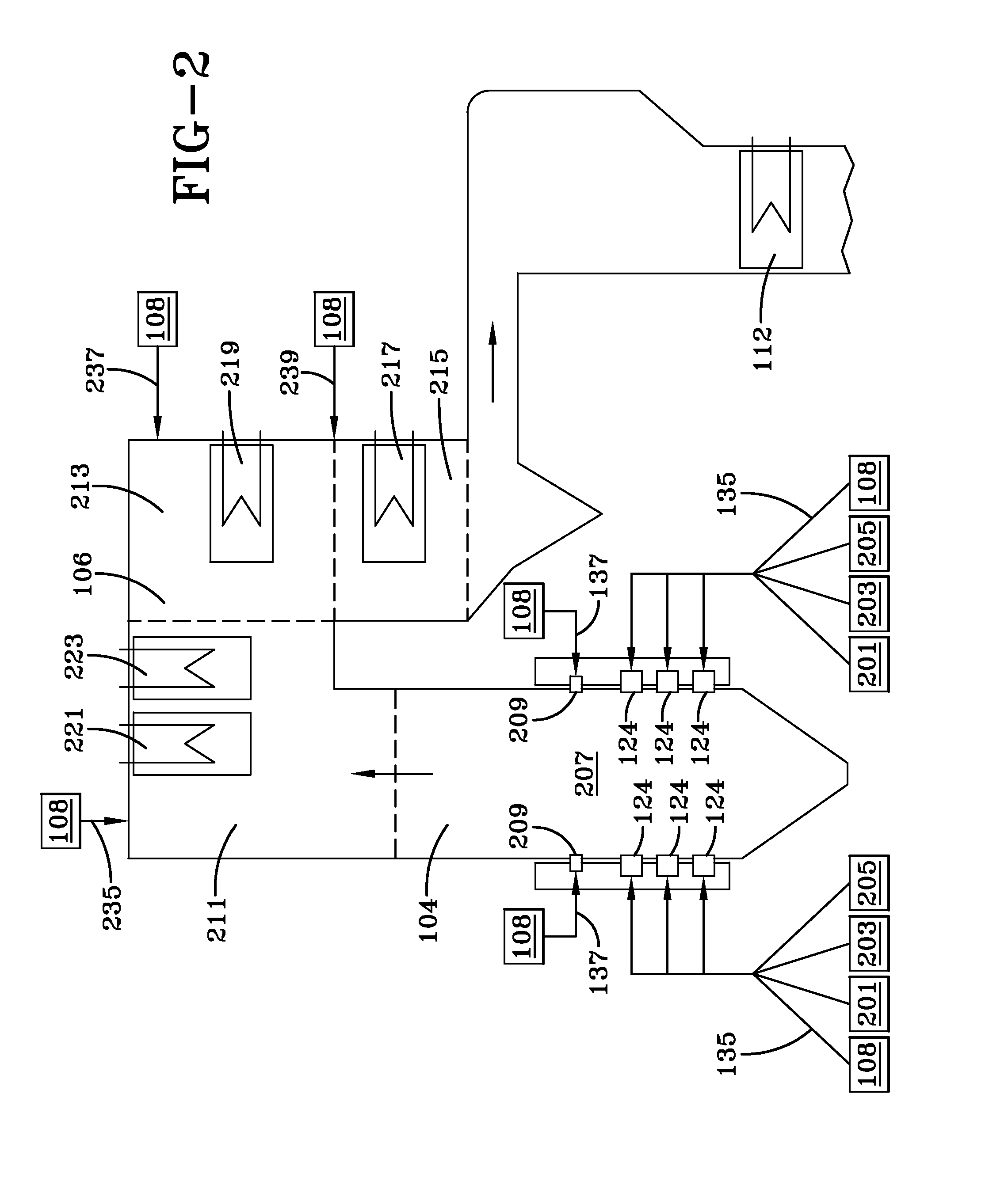
[0046]FIG. 5 shows a representative boiler with four zones (A, B, C, and D). Zone A represents the furnace 104. Zone B represents the secondary superheater and reheater, corresponding to the secondary superheating / reheat zone 211. Zone C represents the primary superheater and reheater, corresponding to the a primary superheater zone 213. Zone D represents the economizer section of the overall boiler, corresponding to an economizer zone 215. Each zone A, B, C and D is encompassed by a dotted line. Table 1 details the analysis of a high volatile bituminous coal. Table 2 shows the absorbed heat duty for each zone outlined in FIG. 5. Table 3 shows the zonal heat and material balances for the different process configurations for the coal combustion defined in Table 1 and 2.

TABLE 1Coal Characteristics for a Typical High Volatile Bituminous CoalProximate Analysis,H2O2.5wgt %Volatile Matter37.6Fixed Carbon52.9Ash7Ultimate Analysis,H2O2.5wgt %C75H25S2.3O26.7N21.5HHV, BTU / lb13000

[0047]Table 2...


PUM

PropertyMeasurementUnit
pressuresaaaaaaaaaa
temperatureaaaaaaaaaa

Abstract

A combustion system having a furnace arranged and disposed to receive solid fuel and oxygen and combust the solid fuel and oxygen to form a flue gas. The system includes a heat exchanger arrangement arranged and disposed to receive heat from the flue gas, where the heat exchanger arrangement has a predetermined heat exchange capacity. A water injection arrangement is arranged and disposed to provide water to the flue gas to controllably adjust the flue gas mass flow rate and temperature to provide the predetermined heat exchange capacity.

Description

CROSS-REFERENCE TO RELATED APPLICATIONS[0001]This Application is related to application Ser. No.______, entitled “OXY / FUEL COMBUSTION SYSTEM WITH LITTLE OR NO EXCESS OXYGEN”, Attorney Docket No. 07228 USA, filed contemporaneously with this Application on Sep. 26, 2008, assigned to the assignee of the present disclosure and which is herein incorporated by reference in its entirety, application Ser. No. ______, entitled “COMBUSTION SYSTEM WITH PRECOMBUSTOR”, Attorney Docket No. 07255 USA, filed contemporaneously with this Application on Sep. 26, 2008, assigned to the assignee of the present disclosure and which is herein incorporated by reference in its entirety, application Ser. No. ______, entitled “OXY / FUEL COMBUSTION SYSTEM WITH MINIMIZED FLUE GAS RECIRCULATION”, Attorney Docket No. 07257 USA, filed contemporaneously with this Application on Sep. 26, 2008, assigned to the assignee of the present disclosure and which is herein incorporated by reference in its entirety, application ...

Claims


Application Information

Patent Timeline
Patent Type & Authority Applications(United States)
IPC IPC(8): F23J15/00
CPCF22B35/00F23J15/02F23J2215/50F23J2900/15061Y02E20/344F23L2900/07005F23L2900/07008F23L2900/07009F23L7/00Y02E20/34
Inventor FOGASH, KEVIN BOYLELI, XIANMING JIMMY
Owner AIR PROD & CHEM INC
Why Eureka
Try Eureka