Mercury removal process
- Summary
- Abstract
- Description
- Claims
- Application Information
AI Technical Summary
Benefits of technology
Problems solved by technology
Method used
Image
Examples
example 1
[0018]To approximately 80 mL of decane, approximately 1 gram of Hg(0) was added. The mixture stirred for several days and the mercury spiked decane was decanted. Approximately 10 g of the spiked decane mixture was added to each of five 30 mL Nalgene® bottles. To the first bottle, nothing was added; to the second bottle, approximately 10 g of deionized water was added; to the third bottle, approximately 10 g of 5.6-6.0% bleach solution was added; to the fourth bottle, approximately 10 g of 5.6-6.0% bleach solution and 0.5 g of 4% hydrochloric acid solution was added; and to the fifth bottle, approximately 10 g of 4.6% sodium chloride solution was added.
[0019]All 5 bottles were shaken on a mechanical shaker for 30 minutes. A sample of the aqueous layer was removed via transfer pipette from bottles 2-5 for mercury analysis using the OhioLumex Cold Vapor Atomic Absorption Spectrometer (CVAA) coupled with the RP-91 attachment which utilizes chemical reduction of mercury via chemical reac...
example 2
[0021]Reagent grade decane, in the amounts shown in Table 2, was spiked with approximately 1.1 ppm of Hg(0) to which was added various quantities of 6 wt. % sodium hypochlorite solution and deionized water in the amounts shown in Table 2. The experiments were performed using the procedure outlined above in Example 1.
TABLE 2Assessing the minimum bleach needed to affect mercury removalAvgDIHg(0)Wt. %% Total HgDecaneBleach*WaterInNaOCIMoleRemovalWt.Wt.Wt.DecaneinRatio(Compared(grams)(grams)(grams)(ppb)MixtureHg:NaOClto Control)10.150.000.00111701:0 0%10.5010.000.0052.93 1:14399.6%10.045.015.1861.49 1:7299.5%10.151.039.02330.31 1:1597.0%10.080.509.53380.151:796.6%10.080.1110.132310.031:279.3%*~6 wt. % stock NaOCl Soln.
[0022]As can be seen from Table 2, the optimal mole ratio of mercury to NaOCl in the decane / Bleach solution mix is at least about 1:7.
example 3
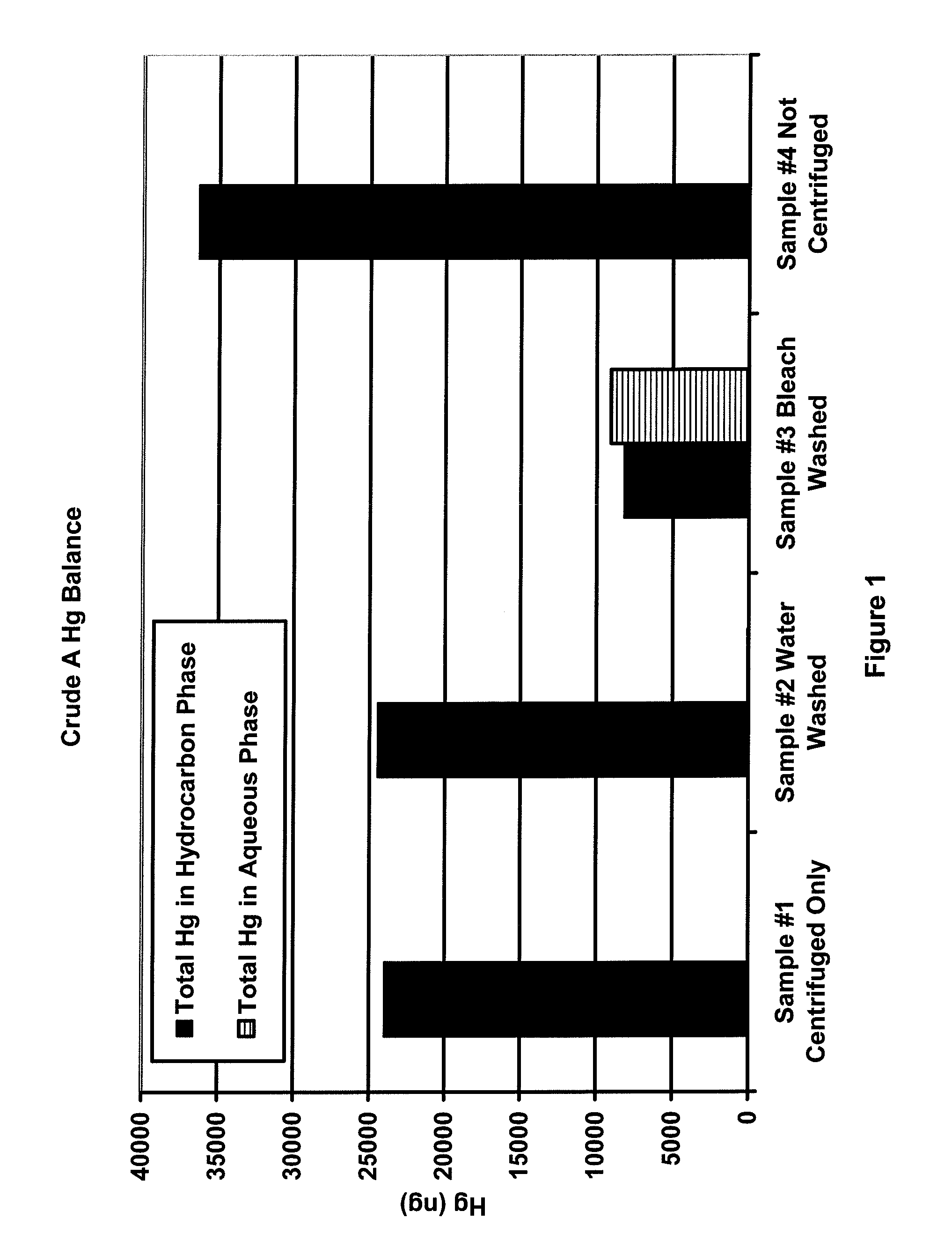
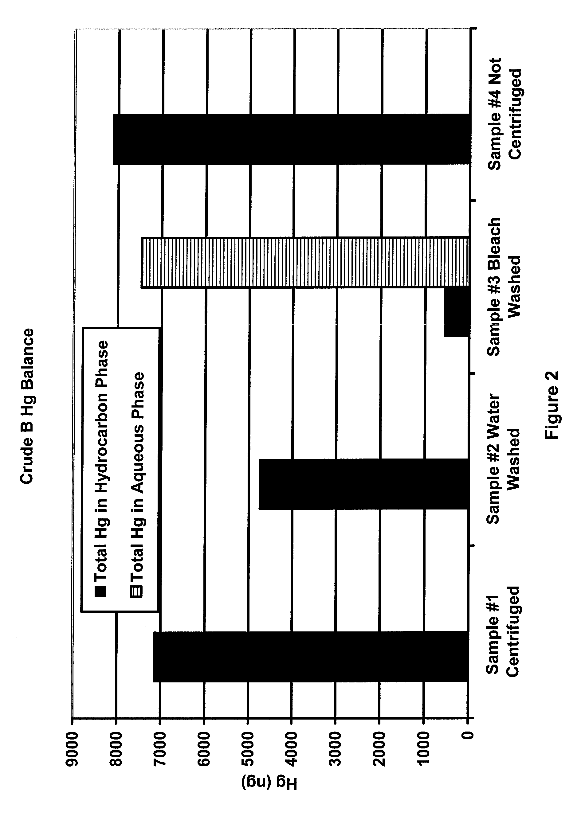
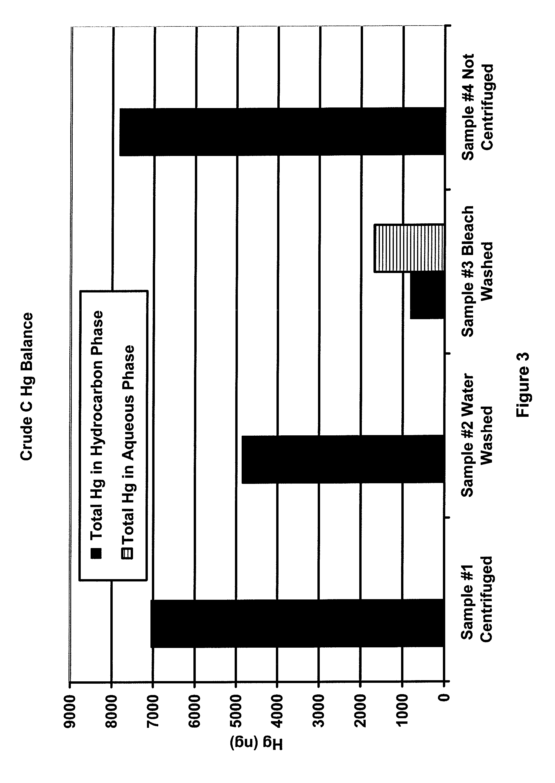
[0023]Samples of three different crude oils (designated as A, B and C) were heated beyond the wax point to obtain representative samples. For each crude oil, four samples of approximately 30 g each were prepared. To three of the four samples, the following bottles were prepared:[0024]1) crude oil only,[0025]2) crude oil and 3 g deionized water, and[0026]3) crude oil and 3 g of 5.6% to 6.0% sodium hypochlorite solution.
[0027]The fourth sample was capped and retained while the first three samples were shaken for 2 minutes. The three shaken samples were centrifuged at 70 degrees C. and 3500 RPM for 20 minutes to effect the separation. All hydrocarbon samples were analyzed for mercury using the OhioLumex CVAA coupled with pyrolysis. All aqueous samples were analyzed for mercury using the OhioLumex CVAA Spectrometer coupled with the RP-91 chemical reduction attachment.
[0028]FIGS. 1-3 are plots of the mass balance of mercury for samples 1-4 for crude oils A, B and C. The black bars in the...
PUM
 Abstract
Description
Claims
Application Information
 - R&D
- Intellectual Property
- Life Sciences
- Materials
- Tech Scout
- Unparalleled Data Quality
- Higher Quality Content
- 60% Fewer Hallucinations
Browse by: Latest US Patents, China's latest patents, Technical Efficacy Thesaurus, Application Domain, Technology Topic, Popular Technical Reports.
© 2025 PatSnap. All rights reserved.Legal|Privacy policy|Modern Slavery Act Transparency Statement|Sitemap|About US| Contact US: help@patsnap.com


