
Preform for molding fiber-reinforced resin beam, process for producing the same, apparatus for producing the same, and process for producing fiber-reinforced resin beam

a technology of fiber reinforced resin and resin beam, which is applied in the direction of transportation and packaging, layered products, and other domestic articles, can solve the problems of high production cost of molded objects, difficult to molded three-dimensional objects, and high materials cost, and achieves the effect of greatly reducing the work of individually arranging release sheets in molds and good quality

Active Publication Date: 2010-04-01
TORAY IND INC
View PDF2 Cites 35 Cited by
  • Summary
  • Abstract
  • Description
  • Claims
  • Application Information

AI Technical Summary

Benefits of technology

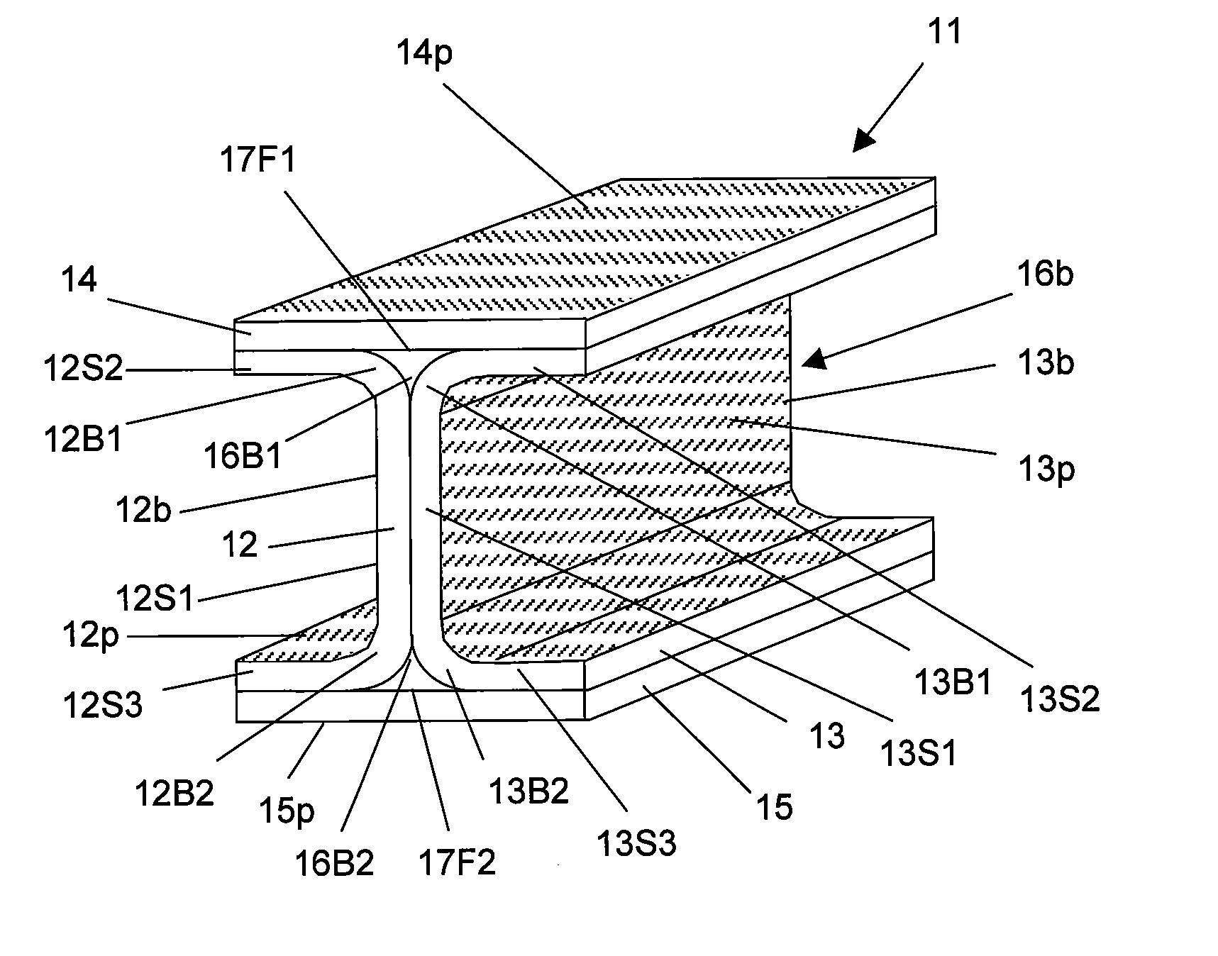
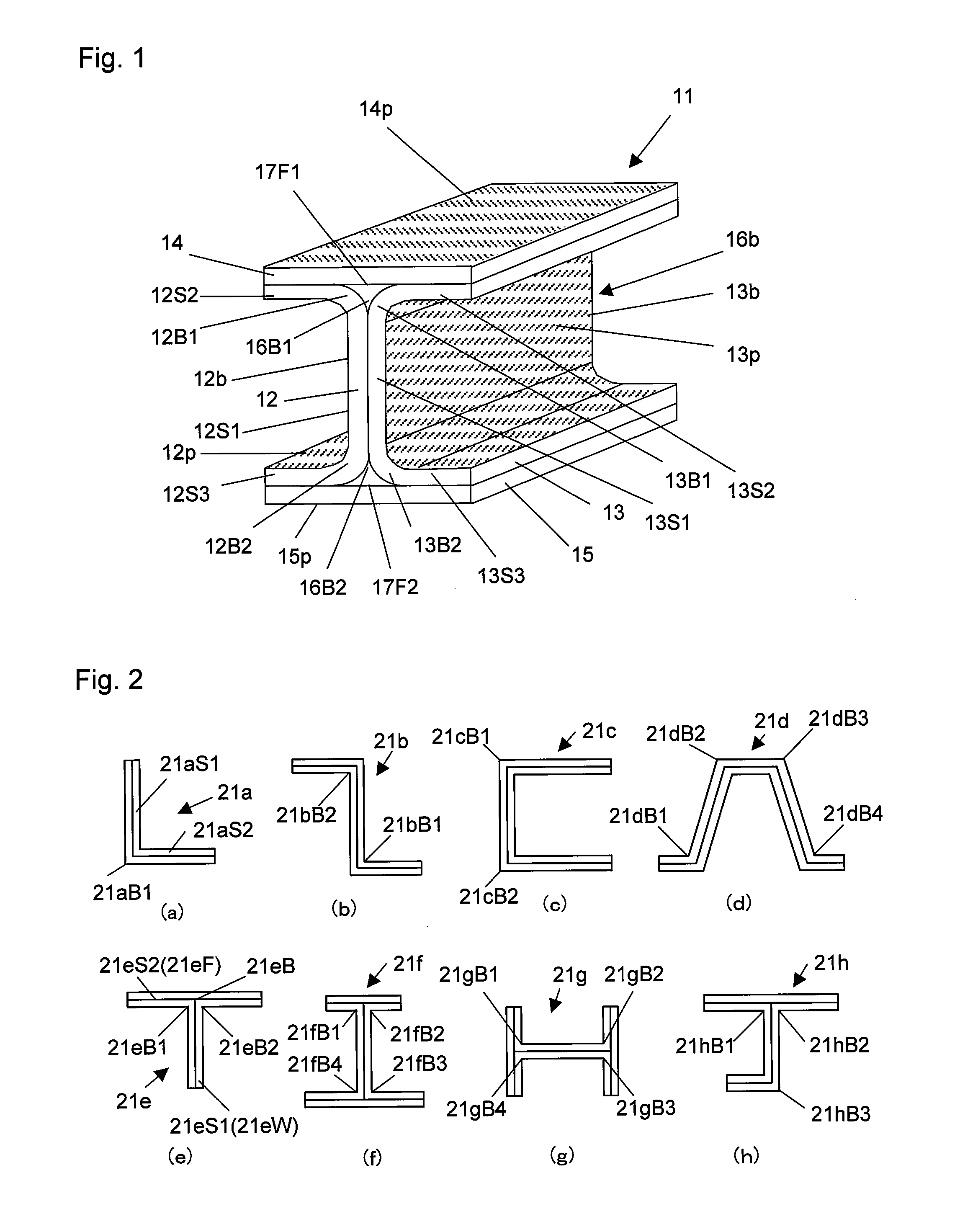
The invention provides a preform for molding a fiber-reinforced resin beam that can be used in a resin transfer molding method. The preform includes a reinforcing fiber beam that has a cross-sectional shape with at least one linear portion and at least one bent portion connected to the linear portion. The preform also has a release sheet bonded and integrated to at least a part of the surface of the reinforcing fiber base. The preform can be produced using a method that involves depositing a reinforcing fiber base with adhesive resin and laminating a release sheet to the surface of the reinforcing fiber base. The preform can be used to produce fiber-reinforced resin beams with improved properties.

Problems solved by technology

However, in the autoclave molding method in which the prepreg sheet is used, there has been a problem that a complicated three-dimensionally shaped molded object is difficult to be molded.
And, since materials cost is too high and molding time is too long, there has been a problem that production cost of the molded object becomes high.
However, by only simply placing a necessary number of the reinforcing fiber cloths in the mold by laying on the other in turn, it is difficult to produce a composite material in which reinforcing fiber cloth has no significant wrinkles and the reinforcing fibers distribute nearly uniformly, and in addition, having a high fiber volume fraction Vf (volume percentage occupied by reinforcing fiber in total volume of molded object).
However, this work for preparing the preform and quality of the preform bring about a great influence to production cost and quality of the composite material.
However, since the release material is, generally, a cloth such as of polyamide or polyester fiber, and media material is, generally, a net-like material (mesh) formed by such as polyamide, by only simply placing these materials at a desired position on a surface of the preform, these are difficult to be fixed at the position.
In particular, in order to arrange and fix the release material to a surface of the preform of complicated shape having a bent portion or branch portion in cross-sectional shape, there has been a problem that considerable work is required, and cost merit of the resin transfer molding method is counteracted.
For that purpose, in most cases, the release material is formed with a material of which thickness is small, not having good adhesive properties, and in addition, which is slippery.
In addition, since the release material is, as the above-mentioned, generally, a woven fabric such as of polyamide or polyester fiber, is poor in stretchability, there was a problem that, unless it is tightly arranged along the shape of preform, when the mold is pushed against the preform, a wrinkle is generated in the release material or a tension of the release material at position of bent portion of the preform is generated, and the mold cannot be pushed against a predetermined position, and the matrix resin is collected in the gap generated between the release material and the preform to form a resin rich portion, and quality of resin molded object formed is deteriorated.
This proposal cannot be said to be sufficient for a requirement to produce a low cost and high quality composite material which is ultimately desired.

Method used


Image

  • Preform for molding fiber-reinforced resin beam, process for producing the same, apparatus for producing the same, and process for producing fiber-reinforced resin beam
  • Preform for molding fiber-reinforced resin beam, process for producing the same, apparatus for producing the same, and process for producing fiber-reinforced resin beam
  • Preform for molding fiber-reinforced resin beam, process for producing the same, apparatus for producing the same, and process for producing fiber-reinforced resin beam

Examples


example 1

Carbon Fiber Cloth

[0428]A unidirectional non-crimp carbon fiber woven fabric having a unit weight of carbon fiber of 190 g / cm2 was prepared by using, as a reinforcing fiber yarn, a carbon fiber yarn having a number of filaments of 24,000, a width of 5.4 mm, a tensile strength of 5.8 GPa and a tensile modulus of 290 GPa as warp, a covering yarn in which 22.5 dtex glass fiber yarn deposited with a coupling agent and covered with 17 dtex nylon 66 filament yarn which is subjected to a scouring as auxiliary yarn of the warp, and 17 dtex nylon 66 filament yarn which is subjected to scouring as weft.

[0429]As an adhesive resin, a particle comprising thermoplastic resin having an average particle diameter of 120 μm and a glass transition temperature of 70° C. was prepared. This adhesive resin was uniformly scattered to both surface of the above-mentioned unidirectional non-crimp carbon fiber woven fabric. The amount scattered of the adhesive resin was made to 13 g / m2 per one surface. The car...

example 2

Bonding and Integrating a Release Sheet to a Reinforcing Fiber Base

[0433]2 release sheets of width 100 mm and length 5,000 mm and 2 release sheets of width 150 mm and length 5,000 mm were prepared by cutting a release sheet made of polyester woven fabric of weight 85 g / m2 and thickness 0.14 mm (Peel Ply 60001 produced by Richmond Aircraft Products, Inc.).

[0434]One of the 2 sheets of the carbon fiber base material of width 100 mm prepared in Example 1 was used as the reinforcing fiber base sheet 142Af shown in FIG. 12, and the other sheet was used as the reinforcing fiber base sheet 142Df. And, one sheet of the carbon fiber base materials of width 150 mm prepared in Example 1 was used as the reinforcing fiber base sheet 142Bf shown in FIG. 12, and the other sheet was used as the reinforcing fiber base sheet 142Cf.

[0435]One of the 2 sheets of the release sheet of width 100 mm prepared was used as the release sheet 142Ap shown in FIG. 12, and the other sheet was used as the release she...

example 3

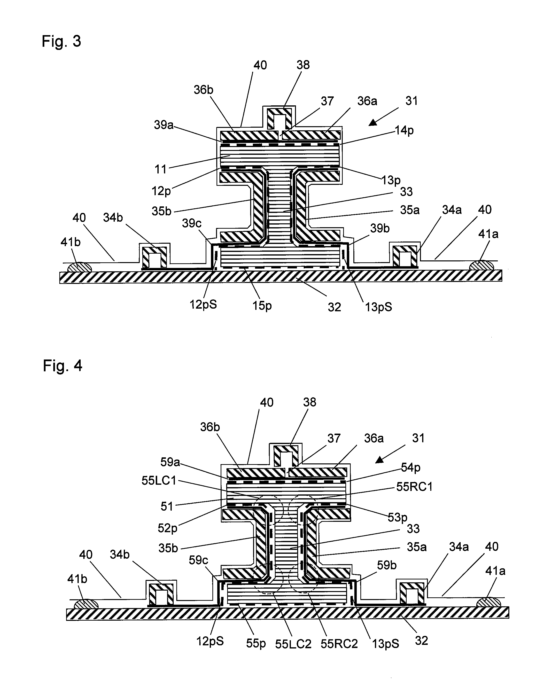
[0452]A fiber-reinforced resin beam was produced from the preform for molding a fiber-reinforced resin beam prepared in Example 2, by using the same molding apparatus shown in FIG. 3.

[0453]In this production, after a matrix resin was injected and impregnated to the preform, it was heated at heating temperature of 130° C. for heating time of 2 hours, to precure the matrix resin. After completing the precure of matrix resin, bagging film and each mold or the like were removed, and demolded. The obtained fiber-reinforced resin beam was heated at a heating temperature of 180° C. for a heating time of 2 hours to carry out postcure of the matrix resin, to complete the molding.

[0454]As a result of inspecting outer surface of the produced fiber-reinforced resin beam, no defect such as a wrinkle or a resin rich was found. By measuring thicknesses of the flange portion and web portion of this fiber-reinforced resin beam in 100 mm interval in the lengthwise direction, the reinforcing fiber vol...


PUM

PropertyMeasurementUnit
volume fraction Vpfaaaaaaaaaa
pressureaaaaaaaaaa
volume fraction Vfaaaaaaaaaa

Abstract

A preform for the molding of a fiber-reinforced resin beam, the preform comprising: a reinforcing-fiber beam which has been formed from a reinforcing-fiber base made up of many reinforcing fibers and has a cross-sectional shape comprising at least one linear part and at least one curved part connected to the linear part; and a release sheet bonded and united through an adhesive resin to at least part of a surface of the reinforcing-fiber base along the lengthwise direction for the base. A process for producing a preform comprises: a step in which a continuous flat reinforcing-fiber base having a release sheet bonded and united to a surface thereof is shaped so that the cross-sectional shape of the base comes to have a curved part to thereby produce a preshaped object; and a preshaped-object uniting step in which the preshaped object is bonded and united to another preshaped object.

Description

FIELD OF THE INVENTION[0001]The present invention relates to a preform for molding a fiber-reinforced resin beam, a process for producing the same, an apparatus for producing the same, and a process for producing a fiber-reinforced resin beam. The preform of the invention for molding a fiber-reinforced resin beam is preferably used when a fiber-reinforced resin beam is produced using a matrix resin by a resin transfer molding method.BACKGROUND OF THE INVENTION[0002]A fiber reinforced resin molded object comprising reinforcing fibers such as carbon fiber, glass fiber or aramid fiber and a resin is, since it is light and has a high durability, used as various structural members, such as, of car and aircraft.[0003]As methods for molding the fiber reinforced resin molded object, for example, an autoclave molding method in which a laminate made by laminating prepreg sheets, which are reinforcing fiber sheets impregnated with a resin, are pressed and heated in an autoclave to cure the res...

Claims


Application Information

Patent Timeline
Patent Type & Authority Applications(United States)
IPC IPC(8): B32B5/12B29C43/18B29C70/34
CPCB29B11/16Y10T428/24124B29C43/12B29C43/224B29C43/30B29C70/443B29C70/542B29C70/546B29C70/547B29C2043/3621B29C2043/3644B29D99/0003B29D99/0014B29K2105/0854B29L2031/003B29L2031/772B29C70/021B29C37/0075Y10T428/249983Y10T428/249982Y10T428/24994
Inventor SUZUKI, TAMOTSUSHINODA, TOMOYUKITSUJI, HARUHIKO
Owner TORAY IND INC
Learn More