Combustion chamber pressure sensor

a pressure sensor and combustion chamber technology, applied in the direction of engine testing, structural/machine measurement, instruments, etc., can solve the problems of measuring element measurement errors, achieve excellent increase the sealing effect and thermal coupling of the sensor body, and easily withstand the temperature inside the combustion chamber

Active Publication Date: 2010-04-08
ROBERT BOSCH GMBH
View PDF10 Cites 8 Cited by
  • Summary
  • Abstract
  • Description
  • Claims
  • Application Information

AI Technical Summary

Benefits of technology

[0005]The combustion chamber pressure sensor according to the present invention makes it possible to retain the advantages obtained by placing the sealing means very much forward on the side of the sensor body facing the combustion chamber pressure, and an excellent thermal coupling of the sensor body to the cylinder head of the internal combustion engine surrounding the receiving bore is obtained at the same time. In comparison with the approaches known from the related art, however, the sensor body is not clamped between the sealing device and the affixation means in the axial direction, so that no axial twisting advantageously occurs between these sections of the sensor body, and neither the torque applied during the screw-fitting nor an axial force resulting therefrom are transmitted to the measuring element. Moreover, it is achieved that forces and deformations that arise in the cylinder head during the combustion process do not lead to measuring errors in the measuring element. A complicated mechanical decoupling of measuring element and sensor body in the interior of the combustion chamber pressure sensor is therefore not necessary.
[0006]The sealing element is advantageously made from a heat-resistant elastic material, so that, for one, the sealing force required for sealing is able to be generated from radial bracing of the sealing element in the cylinder head and, for another, the sealing element easily withstands the temperatures inside the combustion chamber.
[0007]Deposits within the receiving bore of combustion residue on the surface of the sealing element facing the combustion chamber advantageously increase the sealing effect and the thermal coupling of the sensor body to the cylinder head.
[0008]In one advantageous exemplary embodiment, the sealing element takes the shape of a ring and may simply be slipped onto the sensor body, for example.
[0009]By giving the outer diameter of the sealing element a larger diameter than the inner diameter of the receiving bore on the cylinder head, the sealing element is advantageously prestressed against the inner wall of the receiving bore when the sensor body is inserted into the receiving bore, thereby achieving effective sealing.
[0010]In an advantageous manner, the sealing element has high thermal conductivity, so that the combustion chamber pressure sensor is thermally coupled to the cylinder head in a very satisfactory manner, and effective cooling of the combustion chamber pressure sensor with the aid of the cooling means provided on the cylinder of the internal combustion chamber is able to take place. It is especially advantageous to form the sealing element from graphite or Teflon, because these materials have the required elasticity and provide high thermal conductivity at the same time.

Problems solved by technology

If the measuring element is not sufficiently decoupled from the sensor body, these deformations and thermal expansions are transmitted to the measuring element and may cause measuring errors in the measuring element.

Method used


Image

  • Combustion chamber pressure sensor
  • Combustion chamber pressure sensor
  • Combustion chamber pressure sensor

Examples


Embodiment Construction

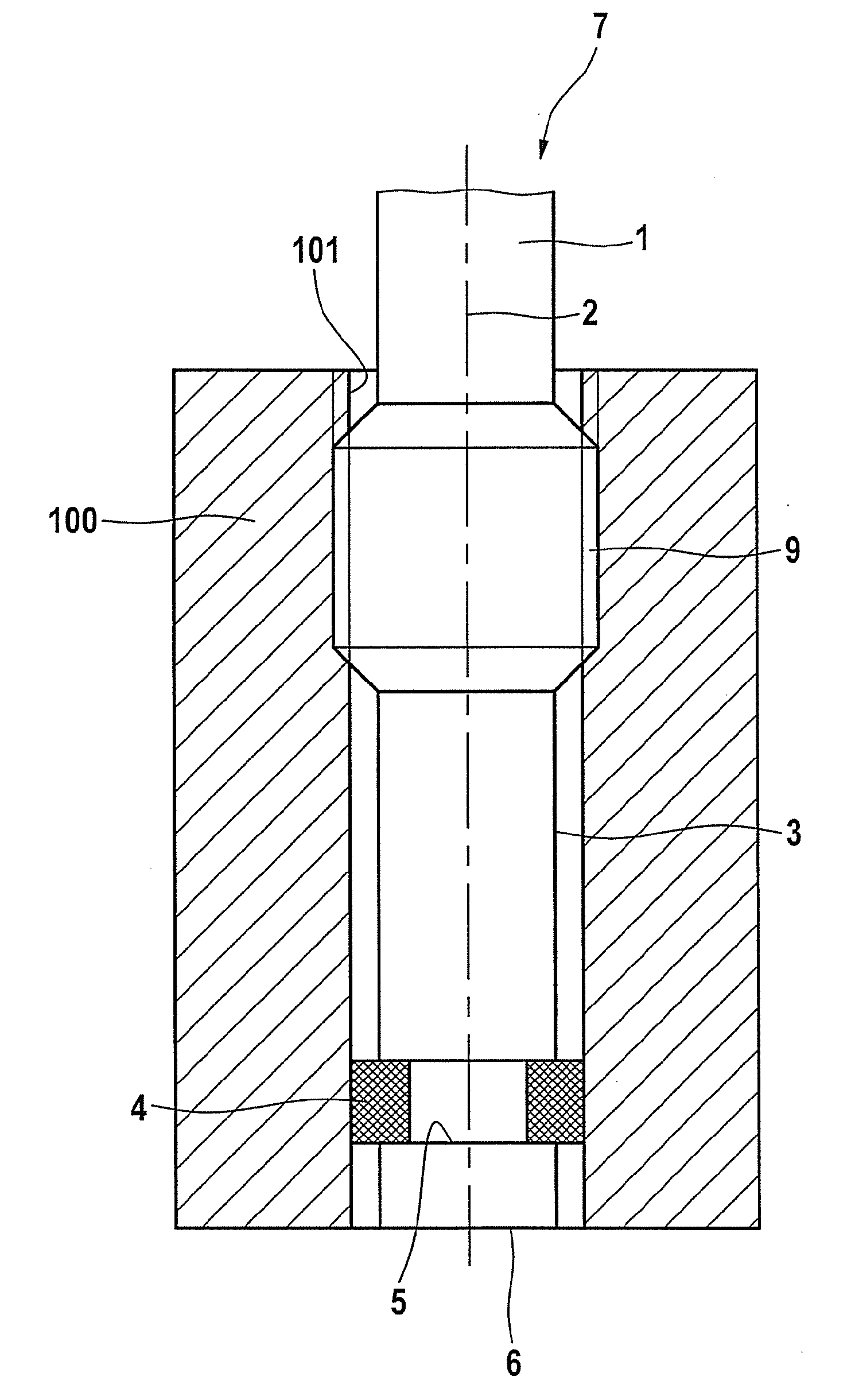
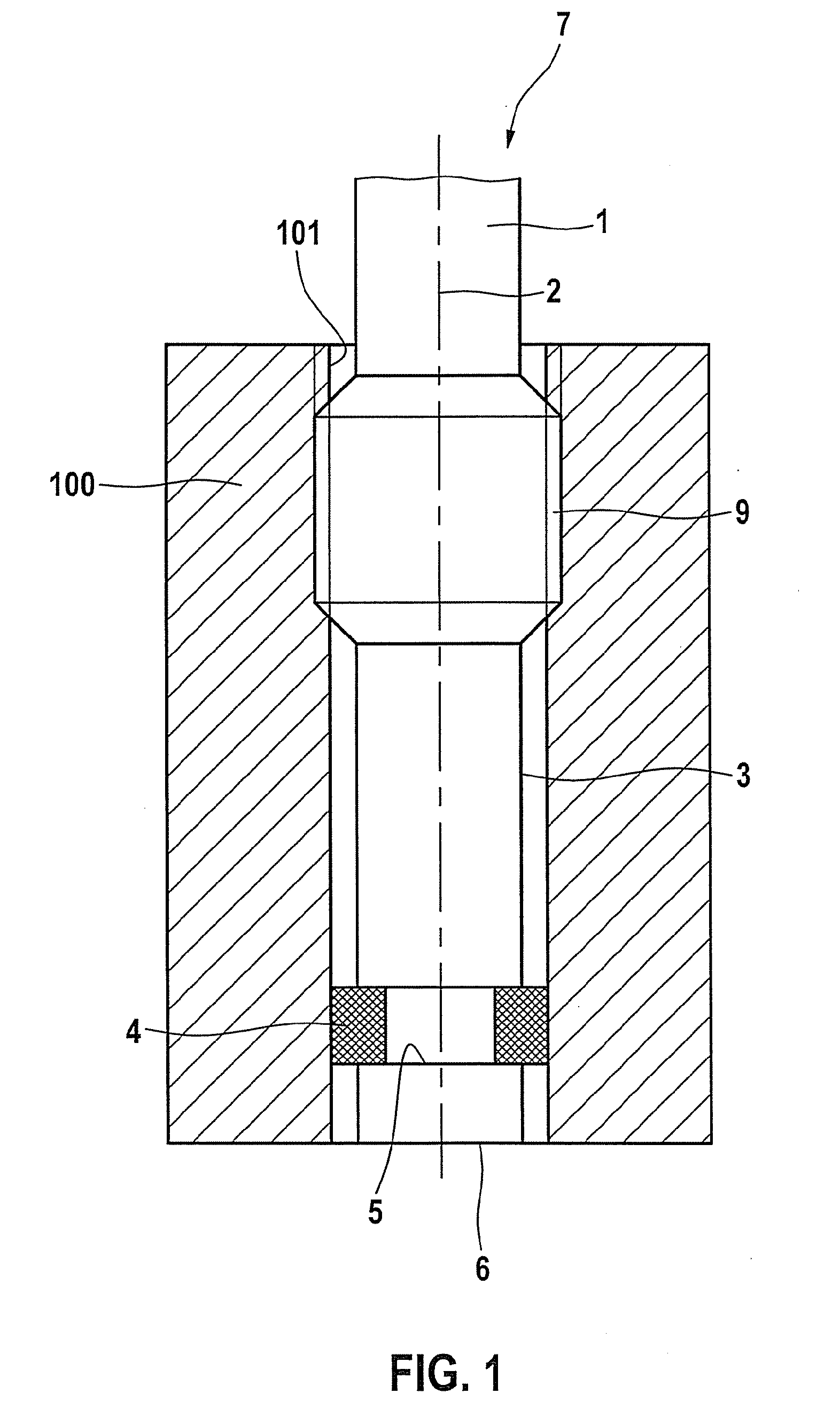
[0014]FIG. 1 shows a first exemplary embodiment of a combustion chamber pressure sensor according to the present invention in a heavily simplified development. The combustion chamber pressure sensor includes an essentially cylindrical sensor body 1, which extends along a longitudinal axis 2 and simultaneously forms the sensor housing of the combustion chamber pressure sensor. The internal structure of the combustion chamber pressure sensor is not shown in FIG. 1 and also not relevant for understanding the present invention. For instance, the combustion chamber pressure sensor may have the internal structure shown in German Patent No. DE 103 12 174, including a transmission plunger and a diaphragm on the side facing the combustion chamber pressure. However, any other types of sensors are possible as well. In addition to the known semiconductor pressure sensor elements, piezoelectric sensor elements, metal diaphragm sensors, optoelectronic sensor elements and others may also be used. ...


PUM


Abstract

A combustion chamber pressure sensor for an internal combustion engine, having a sensor body able to be inserted into a receiving bore of the internal combustion engine, which sensor body has on the side of the combustion chamber a sealing device for sealing the sensor body in the receiving bore, and which sensor body is provided with affixation means for fixing the combustion chamber pressure sensor in place inside the receiving bore. The sealing device includes at least one separately produced heat-resistant elastic sealing element, which is disposed around an outer jacket of the sensor body.

Description

BACKGROUND INFORMATION[0001]The use of combustion chamber pressure sensors for detecting the pressure prevailing in the combustion chamber of an internal combustion engine is already known. Known combustion chamber pressure sensors usually have a longitudinal sensor body, which can be placed into a receiving opening on the cylinder head of the internal combustion engine. Such a combustion chamber pressure sensor is described in German Patent No. DE 103 12 174, for instance, which describes a combustion chamber pressure sensor whose housing forms a bore hole into which a transmission plunger made of ceramic material is inserted, whose one end is sitting on a measuring element and acting on it such that a measuring signal is generated which is proportional to the pressure to be detected, and whose other end is resting on a diaphragm sealing the bore.[0002]German Patent No. DE 10 2005 025 062 describes a combustion chamber pressure sensor, in which the sensor element detecting the comb...

Claims


Application Information

Patent Timeline
Patent Type & Authority Applications(United States)
IPC IPC(8): G01M15/08
CPCG01L23/26G01L23/08
Inventor SCHOLZEN, HOLGERLEDERMANN, MARKUS
Owner ROBERT BOSCH GMBH
Why Eureka
Try Eureka