Supercharge Your Innovation With Domain-Expert AI Agents!

Balanced purge slit valve

a slit valve and purge technology, applied in the field of slit valves, can solve the problems of reducing the throughput of the chamber, affecting the sealing effect of the valve,

Inactive Publication Date: 2010-04-08
APPLIED MATERIALS INC
View PDF14 Cites 1 Cited by
  • Summary
  • Abstract
  • Description
  • Claims
  • Application Information

AI Technical Summary

Benefits of technology

The patent describes methods and apparatus for providing gas to a slit valve opening. The slit valve includes a housing with an opening, a door to seal the opening, a gas inlet, and a plurality of nozzles in fluid communication with the gas inlet and the opening. The nozzles are located in the interior sidewalls of the slit valve. An insert is also described that can be placed into the slit valve opening and includes a housing with nozzles and a conduit to provide purge gas to the opening. The technical effects of this patent include improved methods for controlling the gas supply to a slit valve and the ability to purge the valve with a purge gas.

Problems solved by technology

The process gases introduced in the process volume used to deposit or remove materials tend to degrade the compressible sealing device.
Replacement of the vacuum seal is time consuming and decreases throughput of the chamber.

Method used


Image

  • Balanced purge slit valve
  • Balanced purge slit valve
  • Balanced purge slit valve

Examples


example 1

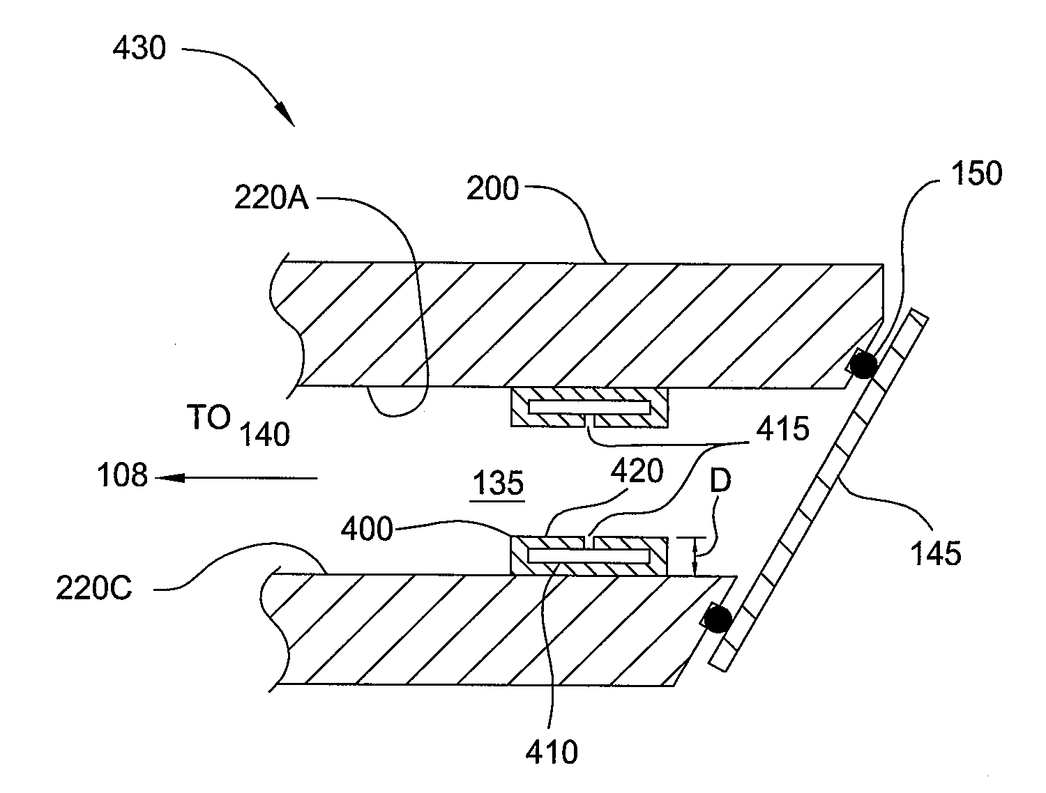
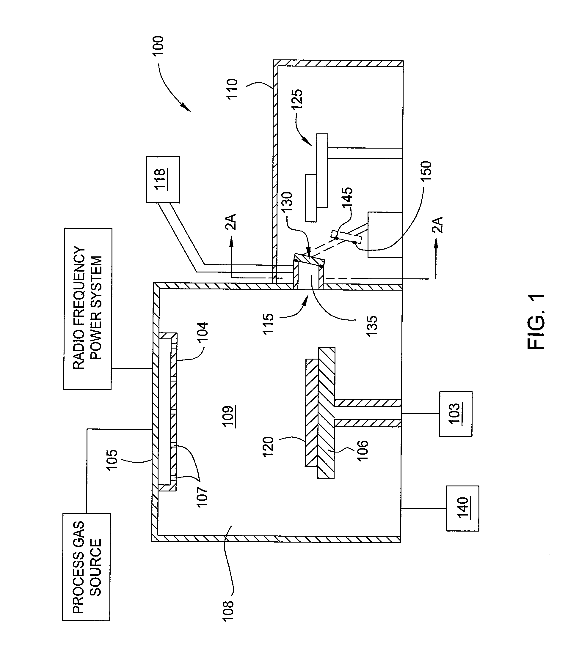
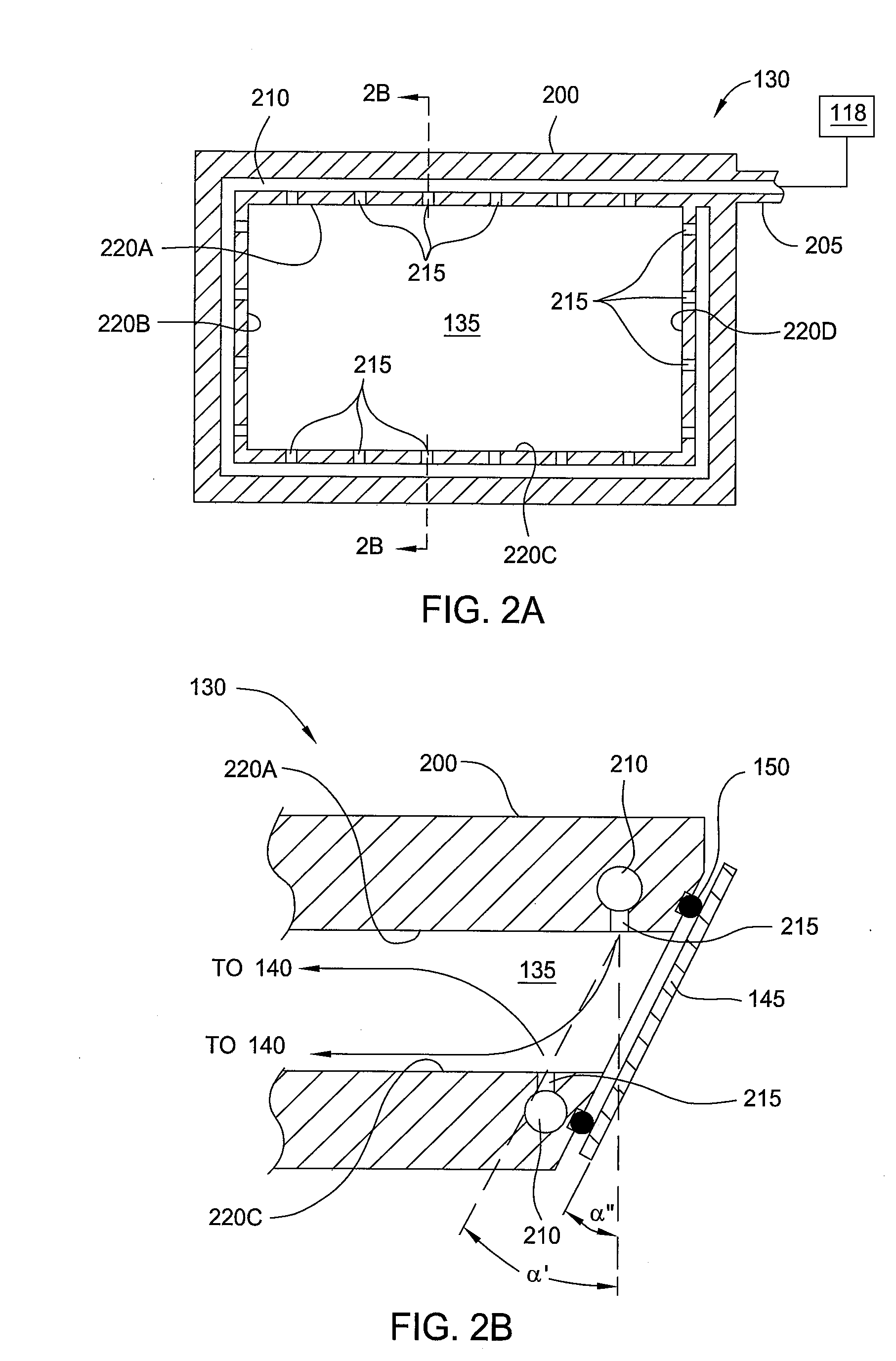
[0038]Example 1 was performed using a slit valve 130 according to embodiments described herein using the same process conditions as described in the control simulation, with the exception of an argon flow at 5 sccm into the opening 135 through nozzles in the interior sidewall 220A and allowed to exhaust to the vacuum pump 140. Process gas concentration was shown to decrease in the opening 135 adjacent the interior sidewall 220A while the process gas concentration across the substrate 120 and other portions of the interior volume 108 remained uniform.

example 2

[0039]Example 2 was performed using a slit valve 130 according to embodiments described herein using the same process conditions as described in the control simulation, with the exception of an argon flow at 5.0 sccm into the opening 135 through nozzles 215 in the interior sidewall 220A. In this example, the opening 135 included a plurality of nozzles 315 in interior sidewall 220C as described in FIG. 3A. The plurality of nozzles 315 were coupled to a vacuum pump to exhaust the opening 135. Process gas concentration was shown to decrease in the opening 135 adjacent the interior sidewall 220A while a slight increase of process gas was detected at the interior sidewall 220C as compared to Example 1. A slight increase in process gas concentration as compared to Example 1 was also detected at the port 115. The process gas concentration across the substrate 120 and other portions of the interior volume 108 remained uniform.

example 3

[0040]Example 3 was performed using a slit valve 130 according to embodiments described herein using the same process conditions as described in the control simulation, with the exception of an argon flow into the opening 135 through nozzles in the interior sidewalls 220A and 220C. An argon flow of 5.0 sccm was provided to the opening 135 and divided such that 2.5 sccm of argon was flowed to the nozzles in the interior sidewall 220A and 2.5 sccm of argon was flowed to the nozzles in the interior sidewall 220C. The argon provided to the opening 135 was allowed to exhaust to the vacuum pump 140. Process gas concentration was shown to decrease in the opening 135 adjacent the interior sidewalls 220A and 220C while the process gas concentration across the substrate 120 and other portions of the interior volume 108 remained uniform.


PUM


Abstract

Methods and apparatus for providing a gas to a slit valve opening are provided herein. In one embodiment, a slit valve is described. The slit valve includes a housing having an opening, the opening defined by a plurality of interior sidewalls and sized to allow a substrate to pass therethrough, a door adapted to selectively seal the opening, a gas inlet formed in the housing, and a plurality of nozzles disposed in or on at least one of the plurality of interior sidewalls, each of the plurality of nozzles in fluid communication with the gas inlet and the opening.

Description

BACKGROUND OF THE INVENTION[0001]1. Field of the Invention[0002]Embodiments of the present invention generally relate to semiconductor processing.[0003]2. Description of the Related Art[0004]As the demand for semiconductor devices continues to grow, there is a constant need to increase manufacturing throughput without sacrificing device quality. Some methods use an apparatus for depositing or removing materials from a surface of a substrate, such as a semiconductor wafer. The apparatus typically includes a chamber having a process volume having a port for transfer of substrates in and out of the process volume. The port is typically selectively sealable by a valve or door having a compressible sealing device in contact with the port and valve or door when closed.[0005]The process gases introduced in the process volume used to deposit or remove materials tend to degrade the compressible sealing device. Over time, the vacuum seal is degraded to a point where replacement of the seal is...

Claims


Application Information

Patent Timeline
Patent Type & Authority Applications(United States)
IPC IPC(8): B65D43/14F16K27/00
CPCH01L21/67126Y10T137/4259
Inventor NEWMAN, JACOBBURNS, DOUGLAS H.
Owner APPLIED MATERIALS INC
Features
  • R&D
  • Intellectual Property
  • Life Sciences
  • Materials
  • Tech Scout
  • Unparalleled Data Quality
  • Higher Quality Content
  • 60% Fewer Hallucinations
Learn More