

Battery system, vehicle, and battery mounted device
- Summary
- Abstract
- Description
- Claims
- Application Information
AI Technical Summary
Benefits of technology
Problems solved by technology
Method used
Image

Examples
first embodiment
[0090]Now, a first embodiment of the invention will be described below with reference to the accompanying drawings.
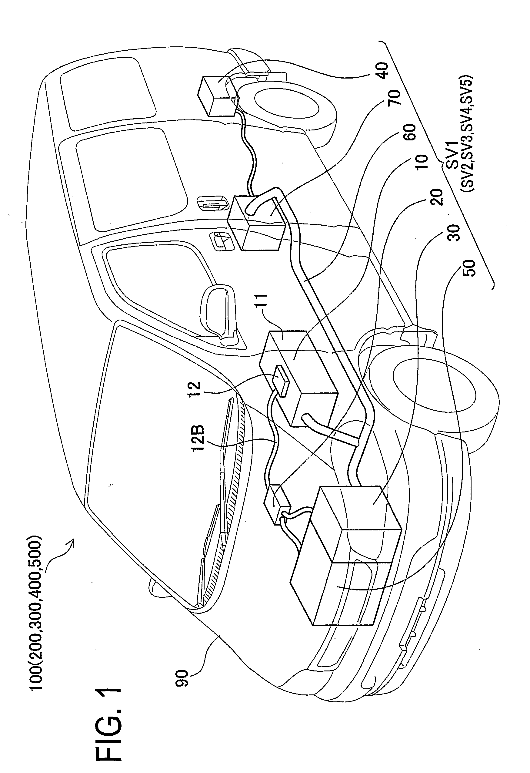
[0091]First, a vehicle 100 according to the first embodiment will be described below. FIG. 1 is a perspective view of the vehicle 100.
[0092]The vehicle 100 of the first embodiment is a hybrid electric vehicle driven by an HV controller 20 using an engine 50, a front motor 30, and a rear motor 40. The vehicle 100 includes a vehicle body 90, the engine 5, the front motor 30 attached thereto, the rear motor 40, a cable 60, an inverter 70, and a battery pack 10.
[0093]The HV controller 20 includes a microcomputer not shown, having a CPU, a ROM, and a RAM and being to be operated according to a predetermined program. The HV controller 20 enables communication with the front motor 30, the rear motor 40, the engine 50, the inverter 70, and a battery monitoring device 12 connected thereto via a communication cable 12B as will be described later, respectively. Thus, the HV contro...
first modified embodiment
[0156]Now, a vehicle according to a first modified embodiment of the invention will be described below with reference to FIGS. 1 and 11.
[0157]A vehicle 200 of the first modified embodiment has the same structure as that of the above first embodiment except for contents regarding the charge and discharge control of the vehicle battery system. Specifically, in the T1 mode of the first embodiment, the upper limit discharge current IDu by 20% lower than the maximum discharge value IDmax in the S mode is provided for controlling the discharge current of the battery pack. On the other hand, in the first modified embodiment, control is performed to equally limit the value of discharge current of the battery pack.
[0158]Accordingly, the following explanation is focused on the differences, and similar or identical parts to those in the first embodiment are not explained or briefly described. It is to be noted that the similar or identical parts provide the same operations and advantages as th...
second modified embodiment
[0170]Next, a vehicle according to a second modified embodiment of the invention will be described below with reference to FIGS. 1 and 12.
[0171]A vehicle 300 of the second modified embodiment has the same structure as that of the above first embodiment except for contents regarding the charge and discharge control of the vehicle battery system. Specifically, the second modified embodiment differs from the first embodiment in that a U1 mode is provided in addition to the S mode and T1 mode of the first embodiment.
[0172]Accordingly, the following explanation is focused on the differences, and similar or identical parts to those in the first embodiment are not explained or briefly described. It is to be noted that the similar or identical parts provide the same operations and advantages as those in the first embodiment. The same contents are explained with the same reference signs.
[0173]The vehicle 300 of the second modified embodiment includes a vehicle battery system SV3 which contro...
PUM
 Abstract
Description
Claims
Application Information