
Optical receiver able to prevent los alarm from malfunctioning

a technology of optical receiver and los alarm, applied in the field of optical receiver, can solve the problems of difficult application of small sized optical receiver optical module, severely restricted lead pin count, etc., and achieve the effect of small siz

Active Publication Date: 2010-04-08
SUMITOMO ELECTRIC IND LTD
View PDF12 Cites 13 Cited by
  • Summary
  • Abstract
  • Description
  • Claims
  • Application Information

AI Technical Summary

Benefits of technology

[0009]In the present invention, because the level monitor and the squelching unit are provided in a secondary path different from a primary path connecting the PD with the main amplifier in the AC mode and the squelching unit fixes the output of the pre-amplifier in the preset voltage when the level monitor detects the absence of the input optical signal, the second order response inherently appeared in the output of the receiver optical module is effectively prevented even when the receiver optical module includes a plurality of circuit units each accompanying with a specific time constant.
[0011]Another aspect of the present invention relates to a receiver optical module that includes a PD, a pre-amplifier, a level monitor and a squelching unit. In the present invention, the receiver optical module has limited lead terminals of a power supply terminal, a ground terminal, a bias supply terminal, and a pair of output terminals at most. Because the level monitor and the squelching unit of the present invention are installed within the receiver optical module without any additional terminals; where the outer lead terminals may be limited to those five terminals, which enables the receiver optical module to be small sized and compact.

Problems solved by technology

Moreover, the optical receiver is necessary to detect the signal level in the primary path before the coupling capacitor where the signal is sent by the differential mode, which is hard to apply the small sized receiver optical module where the count of the lead pins is severely restricted.

Method used


Image

  • Optical receiver able to prevent los alarm from malfunctioning
  • Optical receiver able to prevent los alarm from malfunctioning
  • Optical receiver able to prevent los alarm from malfunctioning

Examples


Embodiment Construction

[0021]Next, preferred embodiments according to the present invention will be described in detail. In the description of the drawings, the same elements will be referred by the same numerals or the symbols without overlapping explanations.

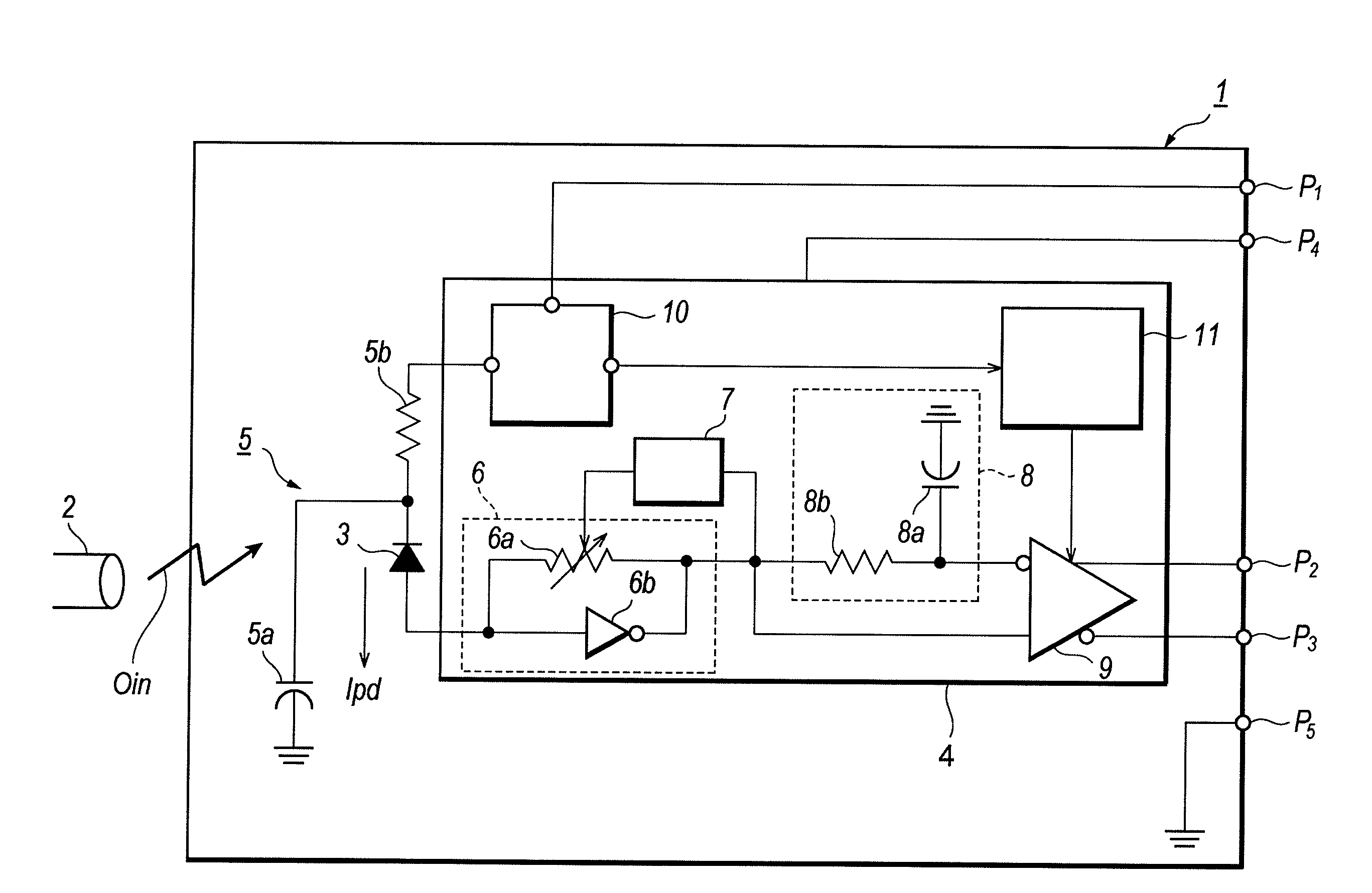
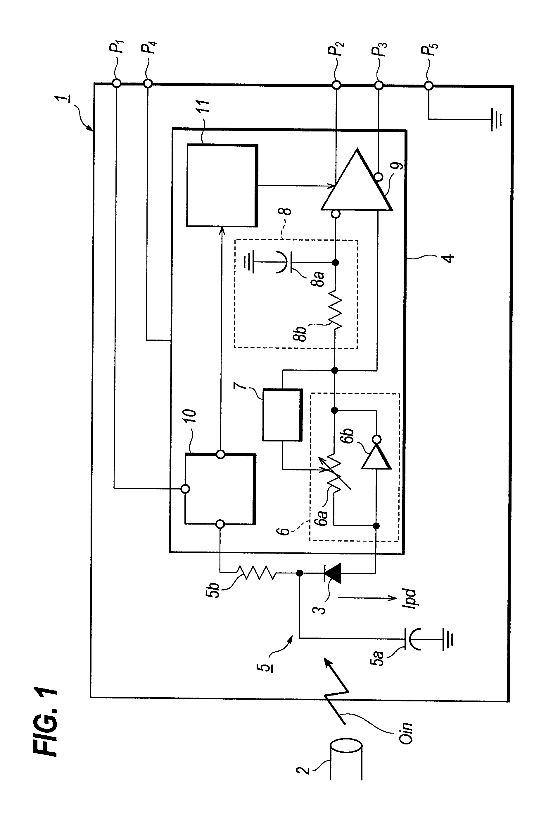
[0022]FIG. 1 is a block diagram of an optical receiver module 1 according to a preferred embodiment of the present invention. The optical receiver module 1 of FIG. 1 includes a photodiode (hereinafter denoted as PD) that receives an optical signal Oin from the optical transmission medium 2 such as an optical fiber and generates a photocurrent Ipd proportional to the optical signal Oin. The anode of the PD 3 is connected to the lead pin P1 through the preamplifier 4 and the filter 5 to receive a bias voltage to the PD 3. The filter 5, which includes a capacitor 5a and a resistor 5b, may eliminate noise containing in the bias voltage. The time constant of the filter 5 is fast enough compared with those of the auto-gain control unit and the averaging u...


PUM


Abstract

An optical receiver able to generate the LOS alarm reliably is disclosed. The optical receiver module in the optical receiver provides a level monitor that monitors the average of the optical input, compares it with a reference and generates a decision signal that is provided to the squelching unit. The squelching unit, by receiving the decision signal, isolates the outputs of the output buffer from the inputs thereof and fixes the outputs of the receiver module in the level “0” or the level “1”. Even the main amplifier is coupled with the receiver optical module in the AC mode; no complicated response appears in the input of the main amplifier.

Description

CROSS REFERENCE TO RELATED APPLICATION[0001]The present application is related to the following commonly-assigned U.S. patent applications: U.S. Ser. No. 11 / 500,325, entitled “OPTICAL RECEIVER WITH MONITORING UNIT AND A METHOD FOR DETECTING CONSECUTIVE IDENTICAL STATE OF OPTICAL SIGNAL” published by US 2007 / 0036541A; and U.S. Ser. No. 11 / 593,138, entitled “OPTICAL RECEIVER RELIABLY DETECTABLE LOSS-OF-SIGNAL STATE” published by US 2007 / 0104494A; all incorporated herein by reference.BACKGROUND OF THE INVENTION[0002]1. Field of the Invention[0003]The present invention relates to an optical receiver, in particular, the invention relates to an optical receiver with a function to generate the LOS alarm reliably.[0004]2. Related Prior Art[0005]Conventional optical receiver applicable to the optical communication system has generally provided the function to generate the LOS (Loss Of Signal) alarm, in which, the optical receiver asserts an alarm when the optical input signal losses. The Uni...

Claims


Application Information

Patent Timeline
Patent Type & Authority Applications(United States)
IPC IPC(8): H04B10/06H04B10/07H03F3/08H04B10/40H04B10/50H04B10/60
CPCH04B2210/071H04B10/07955
Inventor TANAKA, KEIJI
Owner SUMITOMO ELECTRIC IND LTD
Learn More