Magnetic gas engine and method of extracting work

a gas engine and magnetic technology, applied in the field of magnetism and particle dynamics, can solve the problems of limiting the application of other forms of heat energy by practicality, reducing the efficiency of gas turbine engines, and achieving a fraction of the isentropic pressure ratio

Active Publication Date: 2010-04-15
MULDOON PATRICK CRAIG
View PDF8 Cites 6 Cited by
  • Summary
  • Abstract
  • Description
  • Claims
  • Application Information

AI Technical Summary

Problems solved by technology

The main sources of energy for air-breathing engines are hydrocarbon fuels; however, other forms of heat energy can equally be applied limited by practicality.
The performance of jet engines may be understood by means of the laws of thermodynamics, however these laws also restrict the performance to certain upper limits which depend strongly on the maximum temperature the engine can withstand.
Only a fraction of the isentropic pressure ratio is actually achieved since, especially at high Mach numbers, the stagnation pressure losses associated with shocks are substantial.
These assumptions are not, of course, realistic.
In the actual diffuser, there are always irreversibilities due to shocks, mixing, and wall friction.
Departures from isentropic flow in a real nozzle occur due to friction and heat transfer.
However, as shown in FIG. 5, this means a relatively low thrust per unit airflow rate and hence a larger engine for a given thrust.
But the larger the engine, the greater its mass and drag.
It has been mentioned that one of the disadvantages of the ramjet is that its pressure ratio depends on the flight Mach number.
The Ramjet cannot develop takeoff thrust and, in fact, it does not perform well unless the flight speed is considerably above the speed of sound.
However, this introduces the need for power to drive the compressor.
The addition of the turbo machinery, however, entirely changes the characteristic performance of the engine.
Second, the burners are not simple heaters and the composition of the working fluid will change during the combustion processes.
Third, the fluid velocities within the engine are not negligible.
If the fluid velocity in the combustor were actually zero (as constant-pressure combustion requires), it would be impossible to have a stable flame, since the flame propagates relative to the fluid at fairly large velocities.
For a given compressor-pressure ratio, irreversibilities increase the compressor power requirement while at the same time increasing the necessary turbine pressure drop.
Both effects decrease the exhaust kinetic energy, so that overall performance may be expected to be very sensitive to compressor and turbine performance.
The turbine inlet temperature however is limited by the thermal and structural characteristics of current materials.
Although turbine blade cooling allows higher turbine inlet temperatures, detrimental effects do result because of the turbine cooling.
These detrimental effects include added cost for producing turbine blades, reduction in turbine blade reliability, loss of turbine work due to the cooling air bypassing one or more of the turbine stages, losses due to the cooling air being mixed with the hot gas stream, and a decrease in stream enthalpy when the cooling air is mixed with the hot gas stream.

Method used


Image

  • Magnetic gas engine and method of extracting work
  • Magnetic gas engine and method of extracting work
  • Magnetic gas engine and method of extracting work

Examples


Embodiment Construction

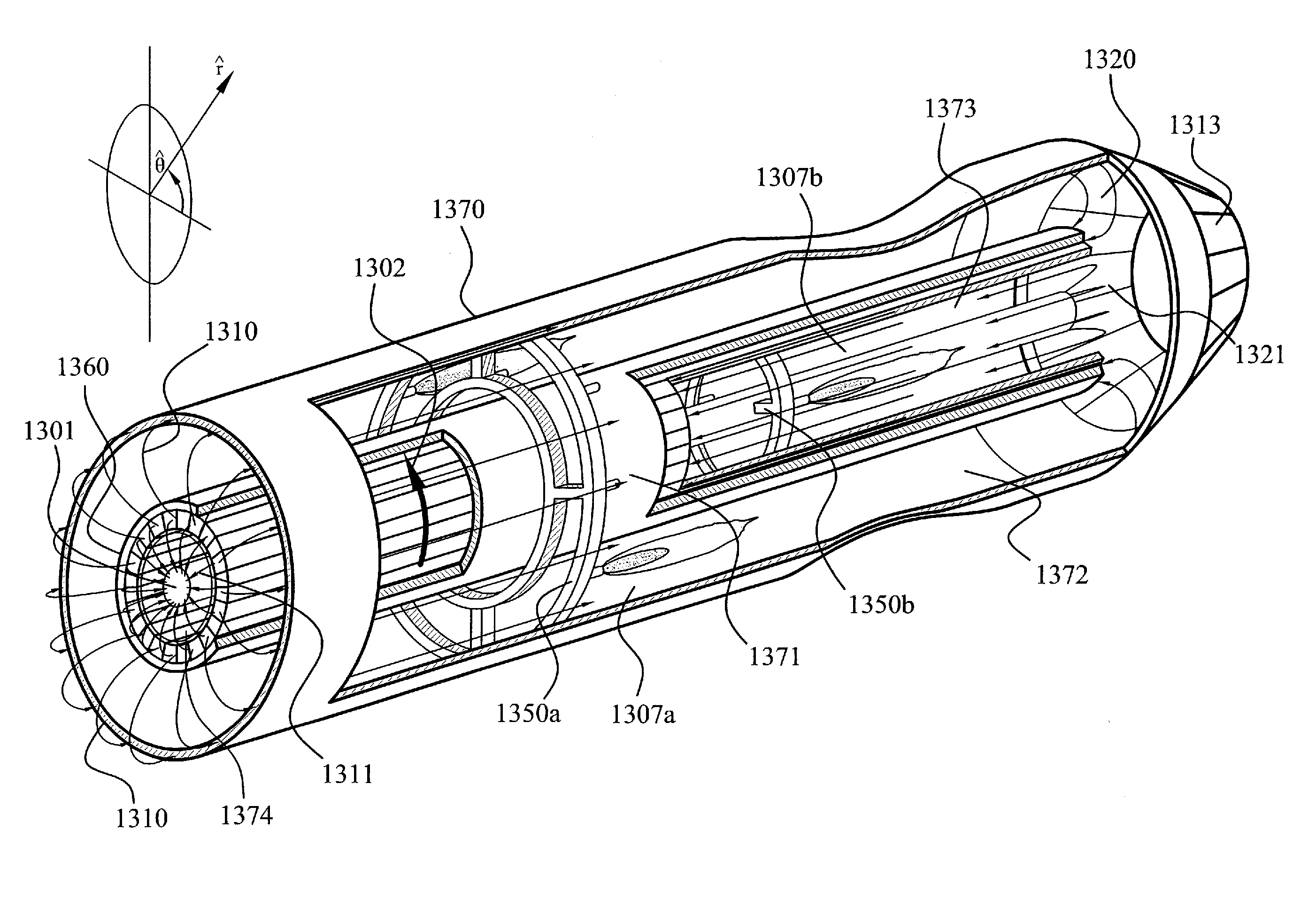
[0092]The present subject matter overcomes the deficiencies in the prior art by introducing or generating charged particles within an air stream and manipulating the air stream with magnetic fields operating on the charged particles. For the purposes of this disclosure charged particles and ionized particles are used synonymously. Embodiments of the present subject matter compress the air stream by accelerating charged particles with a moving magnetic field, where the magnetic field possesses a velocity perpendicular to its flux lines. The increased velocity of the charged particles increases the statistical mean particle velocity and thereby, as discussed previously, increases the pressure of the air stream. The compressed air stream is then heated and expanded through a second magnetic field. The expansion of the air stream substantially increases the velocity of the air stream and the charged particles therein. The interaction of the high velocity charged particles impart a force...


PUM


Abstract

The present subject matter overcomes the deficiencies in the prior art by introducing or generating charged particles in an air stream and manipulating the air stream with magnetic fields operating on the charged particles. Embodiments of the present subject mater compress the air stream by accelerating charged particles with a moving magnetic field, where the magnetic field has a velocity perpendicular to its flux lines. The increased velocity of the charged particles increases the statistical mean particle velocity and thereby increases the pressure in the air stream. The compressed air stream is then heated and expanded through a second magnetic field. The expansion of the air stream substantially increases the velocity of the air stream and the charged particles therein. The interaction of the high velocity charged particles and the magnetic field imparts a force perpendicular to the flux lines, this force powers the movement of the magnetic field and can also be extracted in the form of mechanical work.

Description

RELATED APPLICATIONS[0001]This application is a divisional of and claims priority benefit of co-pending U.S. application Ser. No. 11 / 362,928, entitled “Magnetic Gas Engine and Method of Extracting Work” filed Feb. 28, 2006, now U.S. Pat. No. 7,602,096, which claims the benefit of U.S. Provisional Application 60 / 676,946 entitled “Magnetic Gas Engine and Method of Extracting Work” filed May 3, 2005, the entirety of which is incorporated herein by reference.BACKGROUND[0002]In order to facilitate the disclosure to the present subject matter, a brief discussion of thermodynamics of jet engines, magnetism and particle dynamics follow.[0003]Fluid propulsion devices achieve thrust by imparting momentum to a fluid called the propellant. An air-breathing engine, as the name implies, uses the atmosphere for most of its propellant. The gas turbine produces high-temperature gas which may be used either to generate power for a propeller, generator or other mechanical apparatus or to develop thrus...

Claims


Application Information

Patent Timeline
Patent Type & Authority Applications(United States)
IPC IPC(8): F03H1/00
CPCF02K7/00F02K7/10F02K9/00F02K1/00F03H1/00F05D2220/34F02K1/28F03H1/0081F05D2210/12F05D2220/10
Inventor MULDOON, PATRICK CRAIG
Owner MULDOON PATRICK CRAIG
Why Eureka
Try Eureka