Organic electroluminescence device and method of producing organic device

a technology of electroluminescence device and organic material, which is applied in the direction of discharge tube luminescnet screen, discharge tube/lamp details, coating, etc., can solve the problem of shortening the driving lifetime of the device, achieve the effect of reducing the driving voltage, excelling in the driving lifetime, and improving the chemical stability

Active Publication Date: 2010-04-15
MITSUBISHI CHEM CORP
View PDF10 Cites 13 Cited by
  • Summary
  • Abstract
  • Description
  • Claims
  • Application Information

AI Technical Summary

Benefits of technology

[0024]According to the present invention, an organic electroluminescence device that comprises a layer formed by means of polymerization of a polymerizable compound, can suppress rise in the driving voltage at the time of constant-current energization and degradation in brightness at the time of energization, and thus excels in its driving lifetime can be provided.
[0025]In addition, according to the present invention, by a method of producing an organic device that comprises a layer formed by means of polymerization of a polymerizable compound, an organic device of which layers performing major functions have improved chemical stabilities can be easily and efficiently produced.

Problems solved by technology

However, there were problems in the techniques of the above-mentioned Patent Document 1 and Non-Patent Document 1, in which an organic layer is formed by polymerizing a polymerizable compound.
This makes rise in the driving voltage of the resultant device at the time of constant-current energization and decrease in the brightness stability at the time of energization, which leads to a shortened driving lifetime of the device.

Method used


Image

  • Organic electroluminescence device and method of producing organic device
  • Organic electroluminescence device and method of producing organic device
  • Organic electroluminescence device and method of producing organic device

Examples


example 1

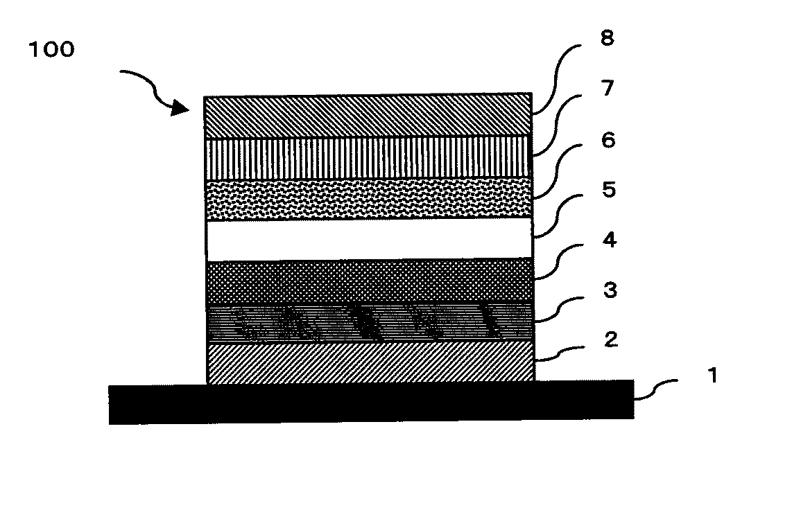
[0400]A glass substrate measuring 17.5 mm×35 mm (and 0.7 mm in thickness) was washed, successively, with a surfactant solution using ultrasonic, with extra-pure water, with extrapure water using ultrasonic and again with extrapure water, followed by drying with nitrogen blow and, finally, ultraviolet ray-ozone cleaning was conducted.

[0401]On this glass substrate, a layer containing a polymerization initiator was formed by wet coating method according to the following procedure.

[0402]Namely, spin coating was carried out under the conditions described below using a coating liquid (composition) that contains a polymer compound (weight-average molecular weight: 29400, number-average molecular weight: 12600, this will be hereinafter referred to as the “compound (P-1)”) having an aromatic amino group with a structure represented by the following formula P-1, as hole-transport agent, and a compound with a structure represented by the following formula A-1 (hereinafter referred to as the “c...

example 2

[0419]A homogeneous, laminated thin film (a thin film in which two layers containing a polymerization initiator and a polymerizable compound respectively are laminated) of which total thickness was 60 nm was obtained under the same condition as used for Example 1, except that the spin-coated film was heated in the air at 180° C. for 1 hour when forming the layer containing a polymerization initiator after irradiated with UV light using a high-pressure mercury lamp in an accumulated light amount of 5 J / cm2 (energy value of 365-nm light).

[0420]The substrate, on which the laminated thin film was formed, was set at a spin coater and 0.2 mL of xylene was dropped thereon in the form of a film, followed by allowing it to stand in the air at 23° C. for 10 seconds. Subsequently, the solvent was dried by conducting spin coating at 1500 rpm for 30 seconds. Then, the film thickness was measured, resulting in the value of 60 nm. In this way, insolubility of the produced film in xylene was verifi...

example 3

[0421]A homogeneous, laminated thin film (a thin film in which two layers containing a polymerization initiator and a polymerizable compound respectively are laminated) of which total thickness was 60 nm was obtained under the same condition as used for Example 1, except that the spin-coated film was heated in the air at 150° C. for 1 hour when forming the layer containing a polymerization initiator after irradiated with UV light using a high-pressure mercury lamp in an accumulated light amount of 5 J / cm2 (energy value of 365-nm light).

[0422]The substrate, on which the laminated thin film was formed, was set at a spin coater and 0.2 mL of xylene was dropped thereon in the form of a film, followed by allowing it to stand in the air at 23° C. for 10 seconds. Subsequently, the solvent was dried by conducting spin coating at 1500 rpm for 30 seconds. Then, the film thickness was measured, resulting in the value of 60 nm. In this way, insolubility of the produced film in xylene was verifi...


PUM

PropertyMeasurementUnit
carbon numberaaaaaaaaaa

Abstract

To provide an organic electroluminescence device that can suppress rise in the driving voltage at the time of constant-current energization and degradation in brightness at the time of energization, and thus excels in its driving lifetime, the organic electroluminescence device comprises: a substrate; an anode and a cathode overlying the substrate; and a plurality of organic layers disposed between the anode and the cathode, and the plurality of organic layers comprise at least: a first layer formed by means of polymerization of a polymerizable compound; and a second layer disposed adjacently to the first layer and containing a polymerization initiator.

Description

TECHNICAL FIELD [0001]The present invention relates to an organic electroluminescence device that comprises a layer formed by means of polymerization of a polymerizable compound and a method of producing an organic device that comprises a layer formed by means of polymerization of a polymerizable compound.BACKGROUND ART [0002]In recent years, electroluminescence devices that uses organic thin films (organic electroluminescence devices) have been developed. As formation methods of organic thin films (organic layers) of organic electroluminescence devices include vacuum evaporation method and wet coating method.[0003]Vacuum evaporation method has advantages of improved charge injection from the anode and / or cathode and easy containment of excitons into the emitting layer, since it is easy to form a laminated structure by the method.[0004]On the other hand, wet coating method has advantages such as no vacuum process, ease in forming large-area devices, and ease in mixing two or more ki...

Claims


Application Information

Patent Timeline
Patent Type & Authority Applications(United States)
IPC IPC(8): H01J1/63B05D5/06
CPCH01L51/0043H01L51/0003H01L51/5088H01L51/5048H10K71/12H10K85/151H10K50/14H10K50/17H10K85/633H10K50/15
Inventor OGATA, TOMOYUKIOKABE, KAZUKIIIDA, KOICHIROYABE, MASAYOSHI
Owner MITSUBISHI CHEM CORP
Why Eureka
Try Eureka