Integrated brushless DC motor and controller

a brushless dc motor and controller technology, applied in the direction of motor/generator/converter stopper, electronic commutator, dynamo-electric converter control, etc., can solve the problem of high price of position sensing devices, achieve improved velocity accuracy, reduce electromagnetic emissions, and improve accuracy

Active Publication Date: 2010-04-15
SMI HLDG
View PDF25 Cites 64 Cited by
  • Summary
  • Abstract
  • Description
  • Claims
  • Application Information

AI Technical Summary

Benefits of technology

[0036]A controller 66 on the board that contains the highly integrated functions of internal Analog to Digital converters 68, PWM (Pulse Width Modulation) registers 70 for driving the power amplifier, internal communication ports 76, and all of the RAM (Random Access Memory) and FLASH non-volatile memory 72 that is typically required for motor control. The software in the controller provides the command and control interfaces for the user and it computes the control algorithm that provides stable motor performance that accurately follows the external commands. The software uses the FLASH memory to store highly configurable control parameter settings that allow the system to be easily configured to perform a wide variety of servo functions.
[0083]The preferred embodiment uses a different technique as shown in FIG. 19. In this method, the servo system is operated in the position loop mode. A position command profile is generated that would be the result of the theoretically perfect velocity which is being commanded. The servo loop follows the position command with some small steady state error, which is typical of stable servo systems. As the revolutions count up, that error remains fixed, regardless of how many revolutions have been made. Consequently, the error in velocity vanishes to zero as operating time moves on. This approach allows the long term accuracy of the velocity to match the accuracy of the oscillator that is running the controller.

Problems solved by technology

In addition, the position sensing device tends to be very expensive.

Method used


Image

  • Integrated brushless DC motor and controller
  • Integrated brushless DC motor and controller
  • Integrated brushless DC motor and controller

Examples


Embodiment Construction

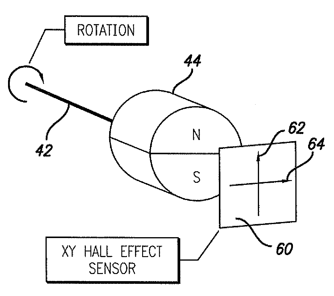
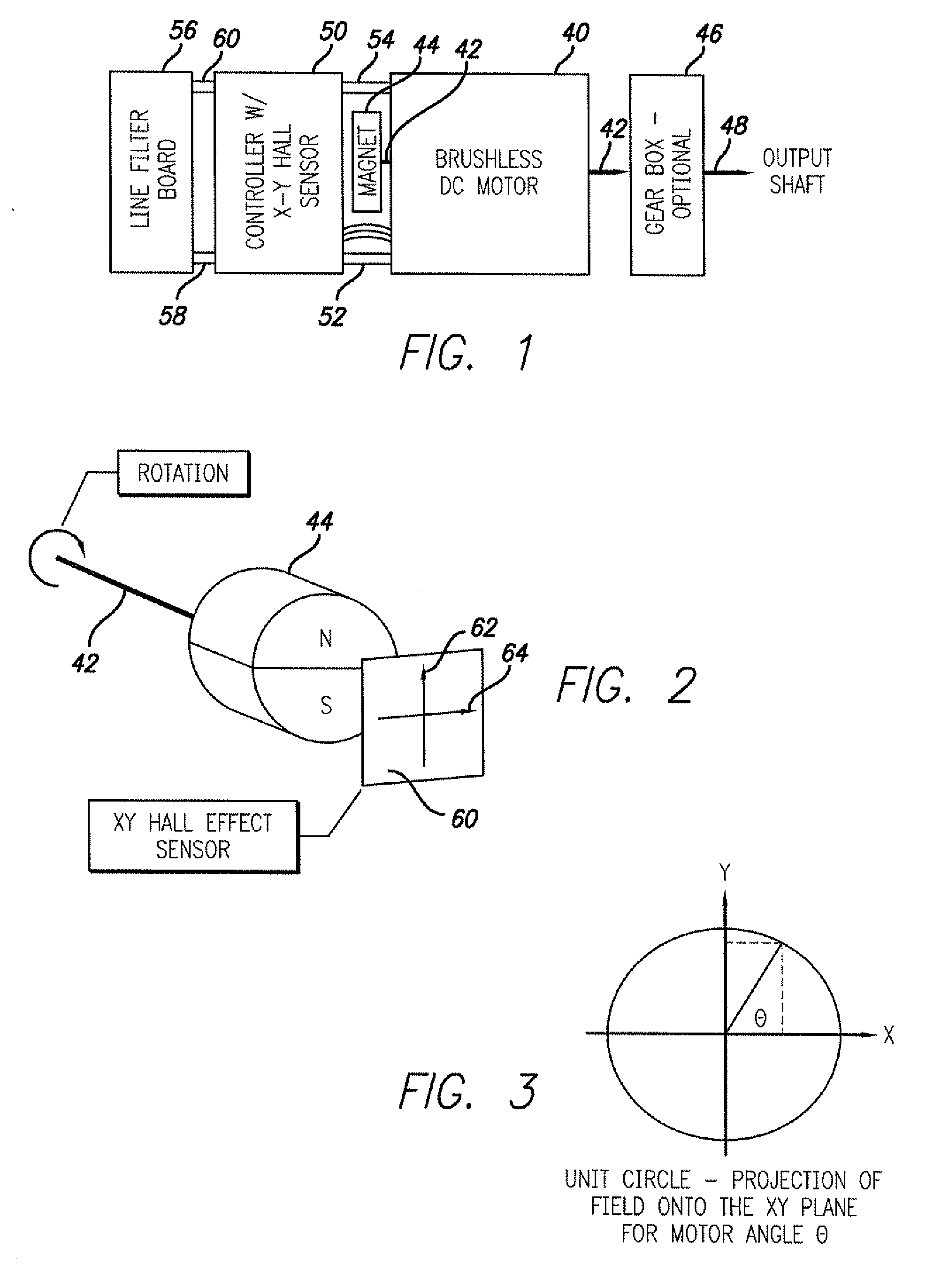
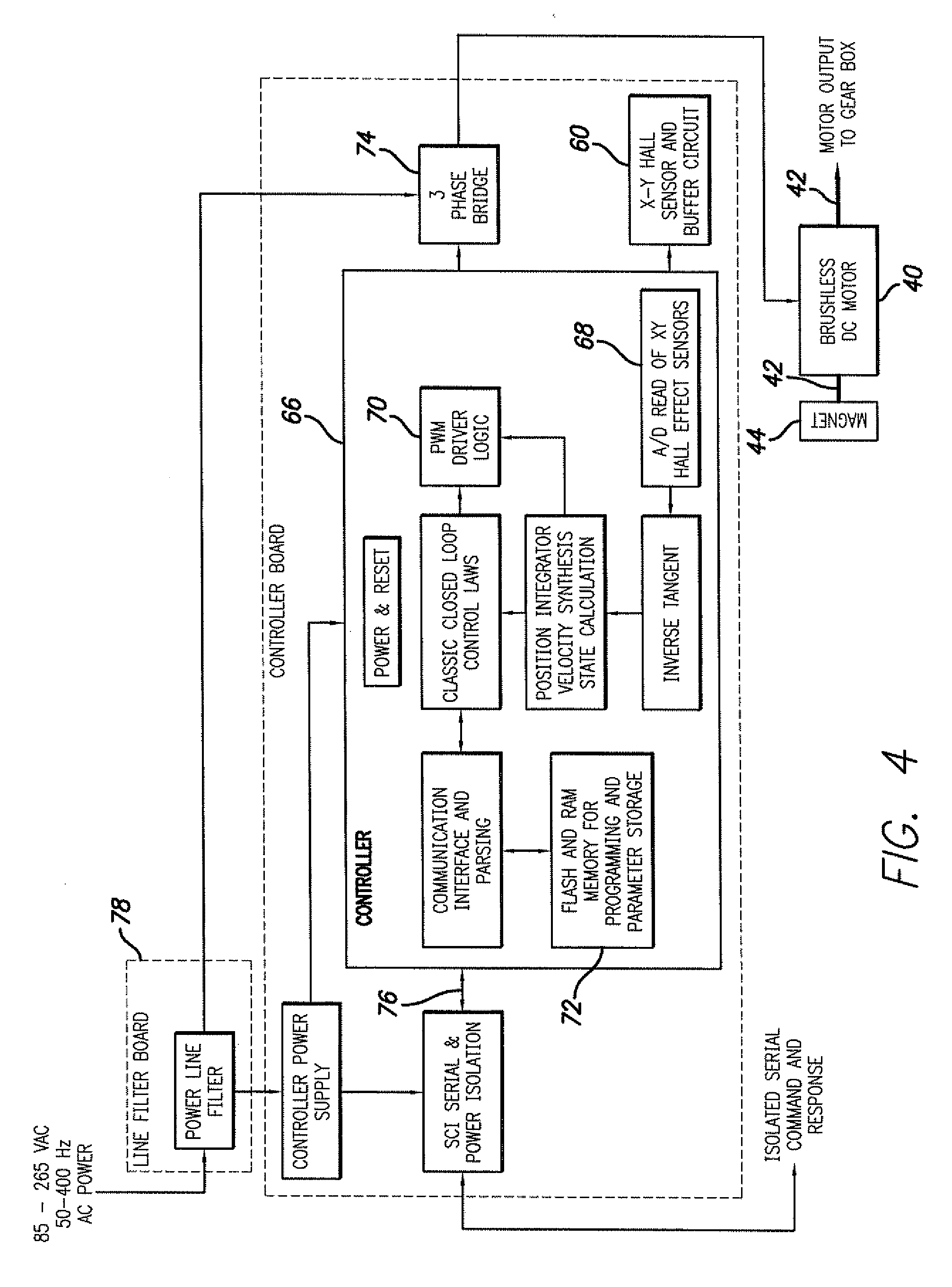
[0028]The objective of high performance at a low cost is achieved by attaching the controller to the motor such that two linear and orthogonally fixed Hall Effect Sensors, packaged in a single monolithic integrated circuit and mounted on the controller board, are located proximate a 2 pole magnet that is fixed to the motors rotor shaft. As the rotor turns, the magnet rotates in a plane orthogonal to the axis of the rotor shaft and the two Hall Effect Sensors produce a Sine and a Cosine signal that is decoded in a controller to give a high resolution signal that is proportional to angular position of the motor shaft. This signal is further decoded to produce the motor state information that is necessary for brushless motor commutation. The high resolution position signal is also used for accurate servo positioning. This combination reduces the necessary connections between the motor assembly and the controller to only the three motor phase wires while allowing all of the advantages a...


PUM


Abstract

An integrated brushless DC motor and controller including a brushless DC motor having a rotating shaft with a 2 pole permanent magnet affixed to the shaft for rotation thereby in a plane orthogonal to the axis of rotation of the shaft. An X-Y Hall Effect Sensor is carried by a controller mounted on a circuit board attached to the motor and the Hall Effect Sensor is positioned proximate the magnet with the Hall Effect Sensor producing the Sine and Cosine components of the magnetic field as the magnet is rotated by the motor shaft. The electronic controller includes software for determining the motor angle and commutation logic from the Sine and Cosine components generated by the Hall Effect Sensor response to the rotating magnetic field. A controller on the board positioned over the rotating shaft contains the highly integrated functions of internal analog digital converters, pulse width modulation registers for driving the power amplifier, internal communication ports and all of the random excess memory and FLASH non-volatile memory that is typically required for motor control.

Description

RELATED APPLICATIONS[0001]This invention is based on Provisional Patent Application No. 60 / 978,070 filed Oct. 10, 2007 and claims the benefit of the filing date thereof.FIELD OF THE INVENTION[0002]The present invention relates to the field of Servo Systems which use brushless DC motors for output drive and modern electronics for the system control.[0003]1. Background of the Invention[0004]DC servo-motors and controllers have a wide variety of application in industry. This combination is commonly used to accurately control the position of an output such as the table on a machine tool or the surface of a fin on a missile. Other common applications include the control of the speed of an output such as a fan or a flow metering pump. The physics and engineering of the basic motor and controller concepts are well known.[0005]As technology and industry progress, the need for greater precision and versatility at lower cost has risen. New controller and sensor technology are enabling the des...

Claims


Application Information

Patent Timeline
Patent Type & Authority Applications(United States)
IPC IPC(8): H02K29/08
CPCH02K29/08H02P6/16H02P6/085
Inventor DELLER, ROBERT W.HEAGEY, ROBERT C.
Owner SMI HLDG
Why Eureka
Try Eureka