Multi-pixel high-resolution three-dimensional imaging radar

a three-dimensional imaging and multi-pixel technology, applied in the field of imaging radar systems, can solve the problems of inability to detect concealed weapons at best, system impracticality, and traditional radar systems are also poorly suited for spectroscopic identification of materials such as explosives

Active Publication Date: 2010-04-15
CALIFORNIA INST OF TECH
View PDF25 Cites 240 Cited by
  • Summary
  • Abstract
  • Description
  • Claims
  • Application Information

AI Technical Summary

Problems solved by technology

For situations that call for remote detection, such as when hidden explosives may be detonated or where clandestine surveillance is warranted, concealed weapons detection is at best extremely difficult to accomplish.
Conventional radars are being widely investigated for this purpose, but stringent spatial resolution requirements make these systems impractical because of the large bandwidths and aperture sizes needed.
Traditional radar systems are also poorly suited for spectroscopic identification of materials such as explosives.
Some progress in through-clothing imaging has been reported using passive thermal detectors in the submillimeter spectrum, but these approaches are lacking in sensitivity and spectral selectivity.
Radar detection systems operating in this manner typically do not derive or utilize range information across the target object (the person).
Thus, such radar systems operating based on reflected power alone are not three-dimensional imaging systems.
However, effective three-dimensional radar imaging systems can be difficult to produce.
However, substantial sensitivity and good resolution are insufficient to reliably detect concealed objects.
Current approaches to THz imaging do not yet meet all of the real-world and often conflicting requirements of standoff range, portability, high speed, penetrability, target identification, and cost.
However, no algorithmic description explaining how radar data is to be used for object detection is given, and no methods of FM-chirp nonlinearity compensation are described.
In real scenarios a coherent radar image will typically exhibit very poor contrast between a concealed object and the surrounding clothing and skin—even for hidden metallic objects such as guns.
For example, while active THz imaging systems using high power coherent illumination and ultra-low-noise heterodyne detection show great promise, they often face operational drawbacks such as requiring cryogenic detectors or bulky laser sources.
A more fundamental difficulty with coherent active imaging is that by relying on a single frequency, target recognition is reliant on an object's contrast and brightness which, in turn, are highly sensitive to incidence angle of radiation, clutter signal from the foreground or background, and interference and speckle effects.

Method used


Image

  • Multi-pixel high-resolution three-dimensional imaging radar
  • Multi-pixel high-resolution three-dimensional imaging radar
  • Multi-pixel high-resolution three-dimensional imaging radar

Examples


Embodiment Construction

1. Overview

[0037]Previously an imaging radar was described that operates at submillimeter wavelengths for applications ranging from concealed weapons detection to planetary trace-chemical identification in U.S. patent application Ser. No. 12 / 135,040, filed Jun. 6, 2008, and entitled “HIGH-RESOLUTION THREE-DIMENSIONAL IMAGING RADAR”, by Cooper et al. (Attorney Docket CIT-4898), which is incorporated by reference herein. Unlike conventional radars, which typically operate below 100 GHz (i.e., wavelengths greater than approximately 3 mm), such a system operating well above this, e.g., 670 GHz, is capable of very high imaging resolution in three dimensions because since its high modulation bandwidth gives higher range resolution and its shorter wavelength gives higher lateral image resolution for any fixed antenna aperture size. Using a novel signal generation architecture, the submillimeter radar is capable of quickly, quietly, and linearly frequency-sweep over a bandwidth of 18 GHz, t...


PUM


Abstract

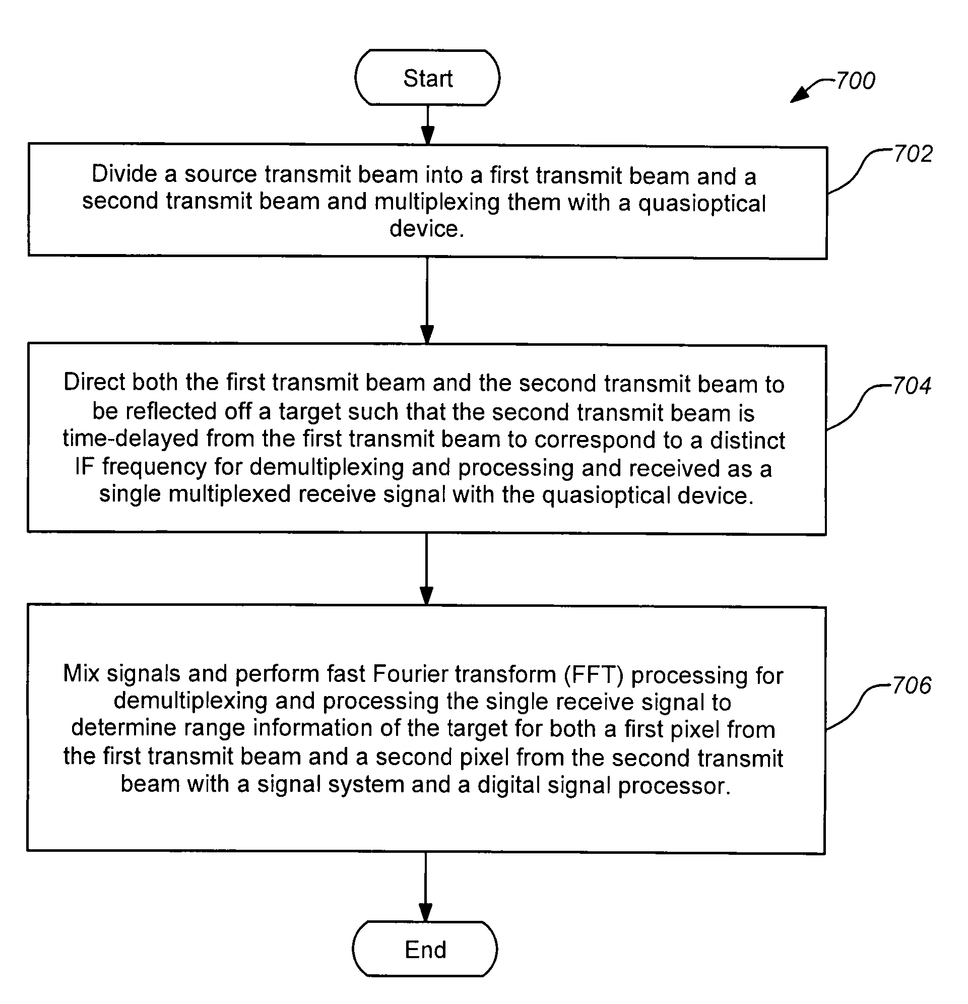
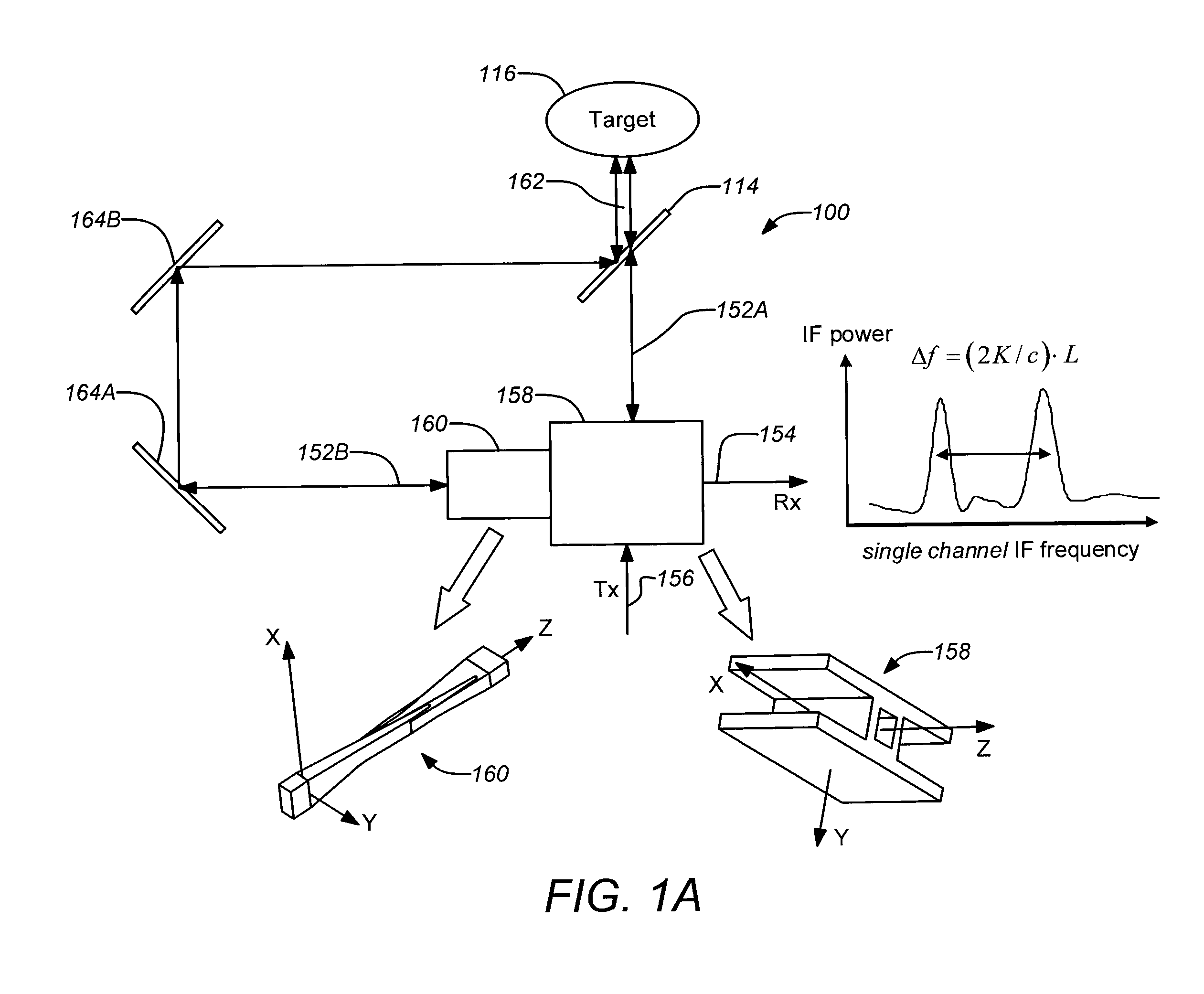
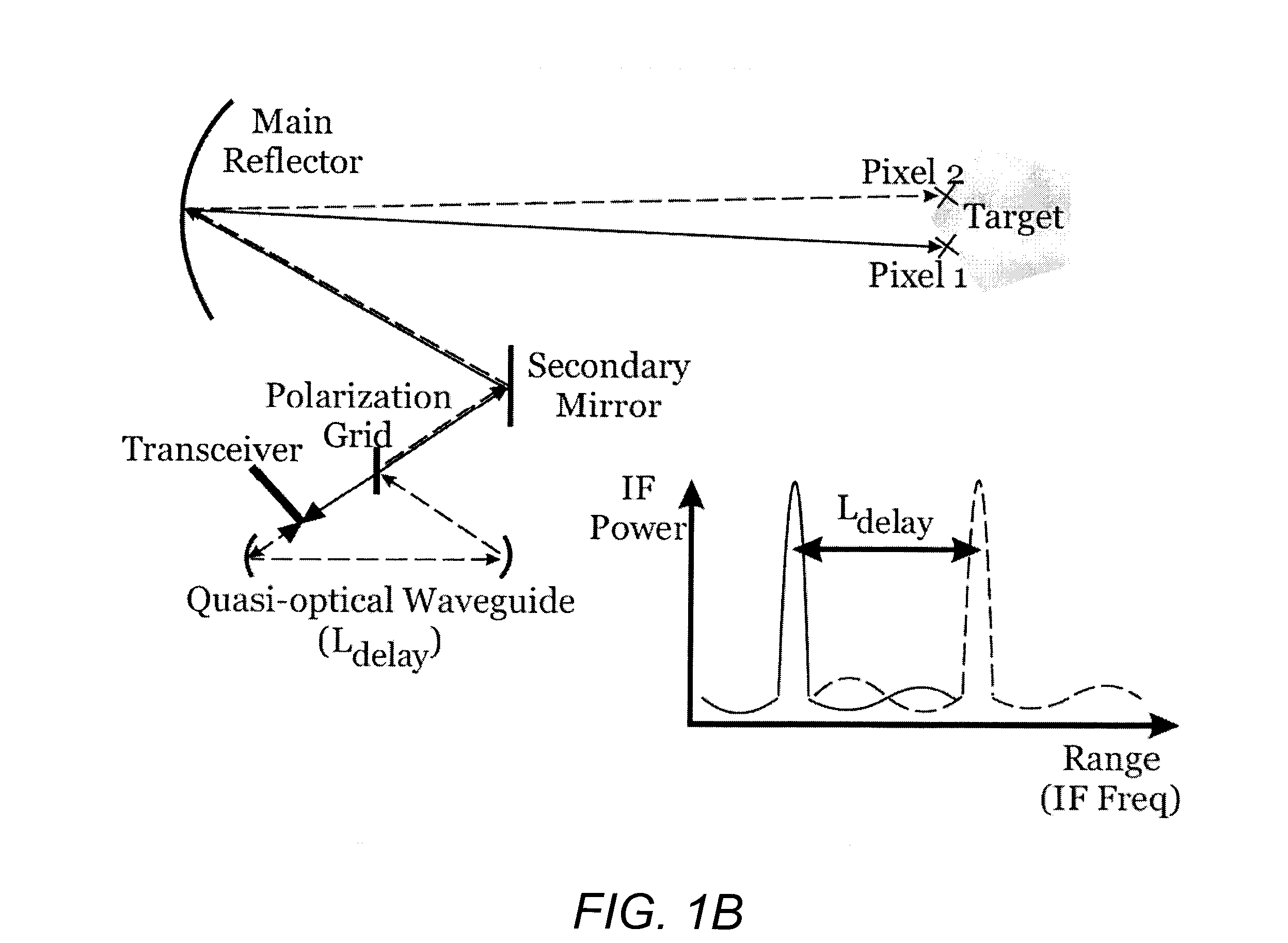
A three-dimensional imaging radar operating at high frequency e.g., 670 GHz radar using low phase-noise synthesizers and a fast chirper to generate a frequency-modulated continuous-wave (FMCW) waveform, is disclosed that operates with a multiplexed beam to obtain range information simultaneously on multiple pixels of a target. A source transmit beam may be divided by a hybrid coupler into multiple transmit beams multiplexed together and directed to be reflected off a target and return as a single receive beam which is demultiplexed and processed to reveal range information of separate pixels of the target associated with each transmit beam simultaneously. The multiple transmit beams may be developed with appropriate optics to be temporally and spatially differentiated before being directed to the target. Temporal differentiation corresponds to a different intermediate frequencies separating the range information of the multiple pixels. Collinear transmit beams having differentiated polarizations may also be implemented.

Description

CROSS-REFERENCE TO RELATED APPLICATIONS[0001]This application claims the benefit under 35 U.S.C. §119(e) of the following U.S. provisional patent application, which is incorporated by reference herein:[0002]U.S. Provisional Patent Application No. 61 / 196,199, filed Oct. 15, 2008, and entitled “A TWO-PIXEL 670 GHZ IMAGING RADAR USING A SINGLE TX / RX MODULE”, by Cooper et al. (Attorney Docket CIT-5254-P).[0003]This application is related to the following co-pending and co-owned application, which is incorporated by reference herein:[0004]U.S. patent application Ser. No. 12 / 135,040, filed Jun. 6, 2008, and entitled “HIGH-RESOLUTION THREE-DIMENSIONAL IMAGING RADAR”, by Cooper et al. (Attorney Docket CIT-4898).STATEMENT OF GOVERNMENT RIGHTS[0005]The invention described herein was made in the performance of work under a NASA contract, and is subject to the provisions of Public Law 96-517 (35 U.S.C. 202) in which the Contractor has elected to retain title.BACKGROUND OF THE INVENTION[0006]1. ...

Claims


Application Information

Patent Timeline
Patent Type & Authority Applications(United States)
IPC IPC(8): G01S13/90
CPCG01S7/024G01S7/03G01S7/35H01Q19/195G01S13/87G01S13/89H01Q19/191G01S13/34
Inventor COOPER, KEN B.DENGLER, ROBERT J.SIEGEL, PETER H.CHATTOPADHYAY, GOUTAMWARD, JOHN S.JUAN, NURIA LLOMBARTBRYLLERT, TOMAS E.MEHDI, IMRANTARSALA, JAN A.
Owner CALIFORNIA INST OF TECH
Why Eureka
Try Eureka