Omni-directional planar antenna

a planar antenna and omnidirectional technology, applied in the structural forms of radiating elements, resonant antennas, substantially flat resonant elements, etc., can solve the problems of large occupied area and increase occupied area, and achieve the effect of convenient implementation and facilitate integration with an integrated circui

Inactive Publication Date: 2010-04-15
ELECTRONICS & TELECOMM RES INST
View PDF14 Cites 77 Cited by
  • Summary
  • Abstract
  • Description
  • Claims
  • Application Information

AI Technical Summary

Benefits of technology

[0015]As described above, the present invention has omni-directional radiation patterns at a high frequency band, thereby archiving minimization and low-price.
[0016]Furthermore, the present invention facilitates integration with an integrated circuit and can be easily implemented even in a silicon semiconductor element.

Problems solved by technology

The omni-directional antenna includes a monopole antenna, a dipole antenna, a helical antenna and the likes, and is disadvantageous in that the occupied area thereof is large.
The planar antenna is disadvantages in that the radiation patterns of a directional antenna in which energy is concentrated in a particular direction is represented rather than omni-directional radiation patterns at a high frequency band, such as a frequency band such as millimeter waves.
However, the planar antenna has a narrow bandwidth of typically 5%, and the structure for feeding the antenna employ a coaxial probe, so that there is a disadvantage in that the occupied area thereof is increased.

Method used


Image

  • Omni-directional planar antenna
  • Omni-directional planar antenna
  • Omni-directional planar antenna

Examples


Embodiment Construction

[0023]The advantages, features and aspects of the invention will become apparent from the following description of the embodiments with reference to the accompanying drawings, which is set forth hereinafter. Therefore, those skilled in the field of this art of the present invention can embody the technological concept and scope of the invention easily. In addition, if it is considered that detailed description on a related art may obscure the points of the present invention, the detailed description will not be provided herein. The preferred embodiments of the present invention will be described in detail hereinafter with reference to the attached drawings.

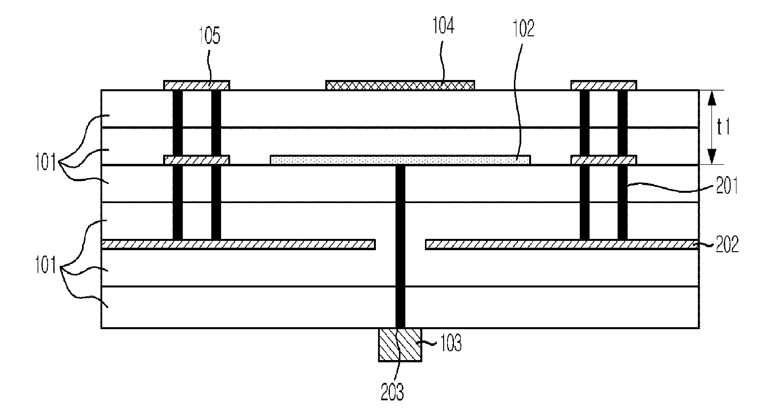
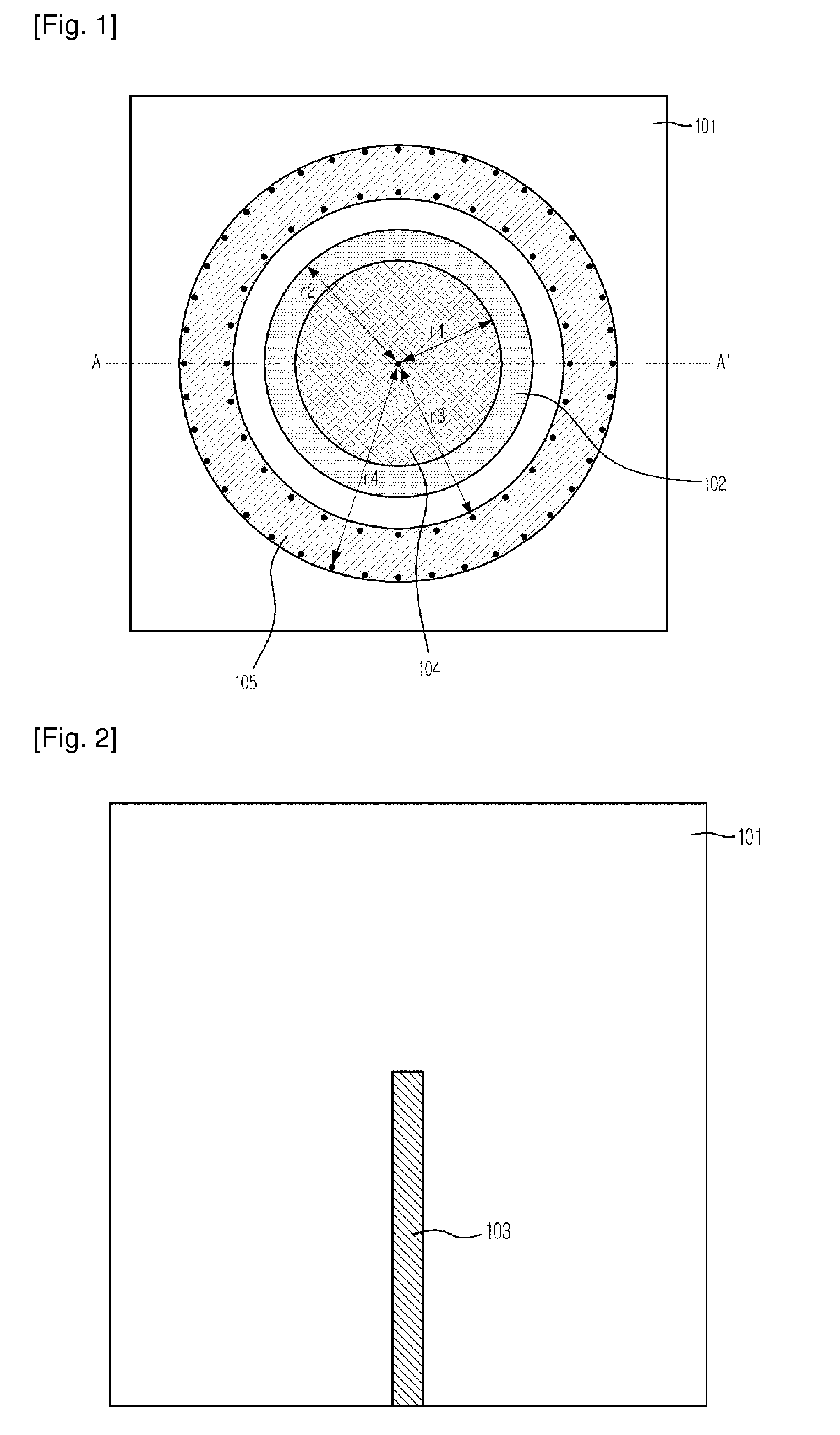
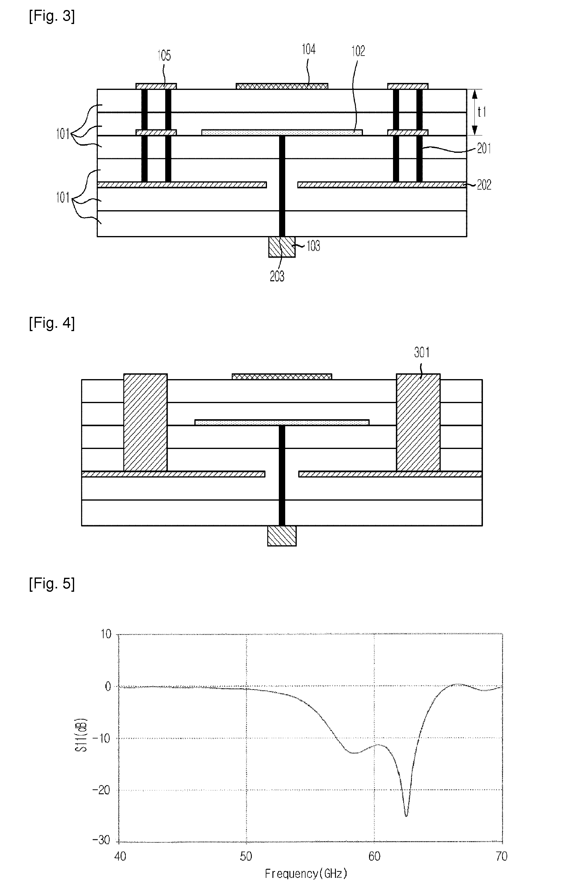
[0024]FIGS. 1 and 2 are plan views of a planar antenna having omni-directional radiation patterns, which is called a planar antenna hereinafter, in accordance with an embodiment of the present invention, and FIG. 3 is a cross-sectional view of FIG. 1 along line A-A′ in accordance with one embodiment of the present invention. In th...


PUM


Abstract

Provided is a planar antenna having omni-directional radiation patterns. The planar antenna includes a circular patch located on one dielectric substrate of the plurality of dielectric substrates; a planar transmission line applied with signals from the exterior; a signal via for coupling the circular patch with the planar transmission line and supplying the signals incoming through the planar transmission line to the circular patch; and a metal ground plane having a slot having a certain shape through which the signal via passes, and located on the dielectric substrate.

Description

TECHNICAL FIELD[0001]The present invention relates to a planar antenna having omni-directional radiation patterns, and, more particularly, to a planar antenna having omni-directional radiation patterns, which includes a parasitic circular patch having a laminated structure at a high frequency band and a circular-shape resonator spaced at a predetermined distance from the parasitic circular patch, thereby making the bandwidth thereof wider.[0002]This work was supported by the IT R&D program for MIC / IITA. [2005-S-046-02, “Development of the basic spectrum resource utilizing technology”].BACKGROUND ART[0003]Until now, in systems for wireless communications, an omni-directional antenna has been used. The omni-directional antenna includes a monopole antenna, a dipole antenna, a helical antenna and the likes, and is disadvantageous in that the occupied area thereof is large.[0004]Meanwhile, in small and lightweight systems, such as cellular terminals, Wireless Local Area Networks (WLAN), ...

Claims


Application Information

Patent Timeline
Patent Type & Authority Applications(United States)
IPC IPC(8): H01Q1/38
CPCH01Q9/0407H01Q13/18H01Q13/08H01Q9/0414H01Q1/38H01Q1/24
Inventor BYUN, WOO-JINKIM, BONG-SUKIM, KWANG-SEONSONG, MYUNG-SUN
Owner ELECTRONICS & TELECOMM RES INST
Why Eureka
Try Eureka