
Double-layer grating

Inactive Publication Date: 2010-04-15
LUMELLA
View PDF6 Cites 20 Cited by
  • Summary
  • Abstract
  • Description
  • Claims
  • Application Information

AI Technical Summary

Benefits of technology

[0007]According to another aspect of the invention, a method for producing an optical grating includes the steps of etching a groove structure having uniformly spaced grooves of predetermined depth and predetermined width in a substrate transparent to optical radiation, with the etching producing sidewalls having a predetermined angle with respect to a major surface of the substrate, depositing a metal layer of predetermined thickness onto the etched groove structure so as to predominantly deposit the metal on top and bottom surfaces of the groove structure while minimizing metal deposits on the sidewalls, and depositing a layer of a dielectric material transparent to optical radiation onto the metal layer so as to at least fill the etched grooves.

Problems solved by technology

The performance of many conventional gratings is limited, particularly in the amount of light diffracted back into the laser gain medium, which impairs efficient lasing operation.

Method used


Image

  • Double-layer grating
  • Double-layer grating
  • Double-layer grating

Examples


Embodiment Construction

[0019]Throughout all the figures, same or corresponding elements may generally be indicated by same reference numerals. These depicted embodiments are to be understood as illustrative of the invention and not as limiting in any way. It should also be understood that the figures are not necessarily to scale and that the embodiments are sometimes illustrated by graphic symbols, phantom lines, diagrammatic representations and fragmentary views. In certain instances, details which are not necessary for an understanding of the present invention or which render other details difficult to perceive may have been omitted.

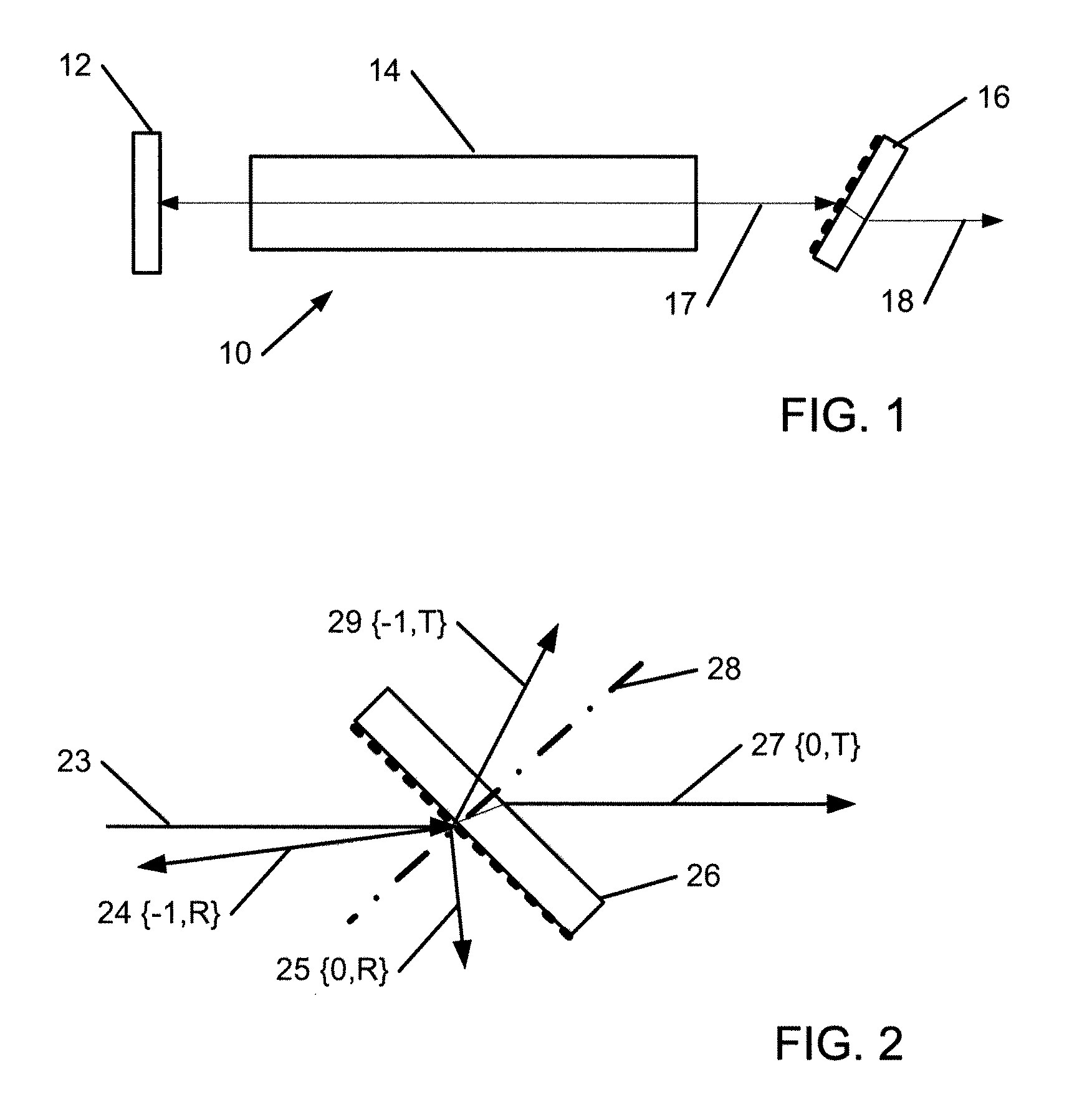
[0020]Turning now to the drawing, and in particular to FIG. 1, there is shown in form of a schematic diagram a conventional laser 10 having a gain section 14 that is wavelength-tuned by a transmission grating 16. A feedback mirror 12 retroreflects light beam 17 back into the cavity 14 for amplification. The output grating 16 partially retroreflects laser light back into cavi...


PUM


Abstract

A double-layer grating structure for efficient retroreflection of incident radiation and efficient transmission of the undiffracted incident radiation is disclosed. The grating is constructed of two spaced-apart layers of periodically arranged metal stripes, wherein the stripes in one layer overlap with gaps between the stripes in the second layer. The layers are encapsulated with a dielectric material. A method for producing such grating is also described.

Description

CROSS-REFERENCE TO RELATED APPLICATIONS[0001]This application claims priority to U.S. Provisional Application Ser. No. 61 / 196,114, filed Oct. 15, 2008, the entire content is incorporated herein by reference.FIELD OF THE INVENTION[0002]Embodiments of the invention generally relate to the fields of optical gratings. More particularly, embodiments of the invention relate to diffraction gratings suited for selecting an output wavelength of a laser.BACKGROUND[0003]Diffraction gratings are used to select a desired wavelength to be amplified and ultimately emitted from a laser cavity. The gratings can be used in any of several types of general configurations (Littman-Metcalf, etc.) based on space constraints and bandwidth of the desired output. Various free space diffraction grating designs are known in the art. The performance of many conventional gratings is limited, particularly in the amount of light diffracted back into the laser gain medium, which impairs efficient lasing operation.[...

Claims


Application Information

Patent Timeline
IPC IPC(8): G02B5/18B44C1/22
CPCG02B5/1866G02B5/1857
Inventor HOOSE, JOHN
Owner LUMELLA
Features
  • Generate Ideas
  • Intellectual Property
  • Life Sciences
  • Materials
  • Tech Scout
  • Unparalleled Data Quality
  • Higher Quality Content
  • 60% Fewer Hallucinations
Learn More