Heat dissipating structure base board, module using heat dissipating structure base board, and method for manufacturing heat dissipating structure base board

a technology of heat dissipation structure and base board, which is applied in the direction of printed circuit board receptacles, electrical apparatus construction details, and semiconductor/solid-state device details. it can solve the problems of limited use of conventional heat dissipation boards for reinforcing peels, difficult to deal with vibration resistance, and similar problems, and achieves the effect of increasing the fixing strength of fixing the lead frame and being difficult to fix at high strength

Active Publication Date: 2010-04-15
PANASONIC CORP
View PDF22 Cites 90 Cited by
  • Summary
  • Abstract
  • Description
  • Claims
  • Application Information

AI Technical Summary

Benefits of technology

[0013]The present invention has been achieved to solve these conventional problems. It is an object of the present invention to provide a heat dissipation structure board, a module using the heat dissipation structure board and a method of manufacturing the heat dissipation structure board using lead frames capable of dealing with high current and having a mechanical strength as wirings constituting a heat dissipation board, intended to increase a fixing strength of fixing the lead frames to other components (such as a fixing strength of an interface between a heat transfer layer and lead frame

Problems solved by technology

However, there is a limit to such a conventional heat dissipation board for reinforcing a peel strength of circuit conductor layer 5.
As a result, it is difficult to deal with vibration resistance (for example, an acceleration test of about 4 G to 20 G is conducted in XYZ directions) as required for on-vehicle devices.
Furthermore, even if a thick material such as a lead frame that can deal with a high current and that has a high strength is employed for conductor circuit 3 and circuit conductor layer 5, simila

Method used


Image

  • Heat dissipating structure base board, module using heat dissipating structure base board, and method for manufacturing heat dissipating structure base board
  • Heat dissipating structure base board, module using heat dissipating structure base board, and method for manufacturing heat dissipating structure base board
  • Heat dissipating structure base board, module using heat dissipating structure base board, and method for manufacturing heat dissipating structure base board

Examples


first embodiment

[0115]A structure of a resin structure employed to increase a strength of a heat dissipation structure board will be described below as a first embodiment of the present invention.

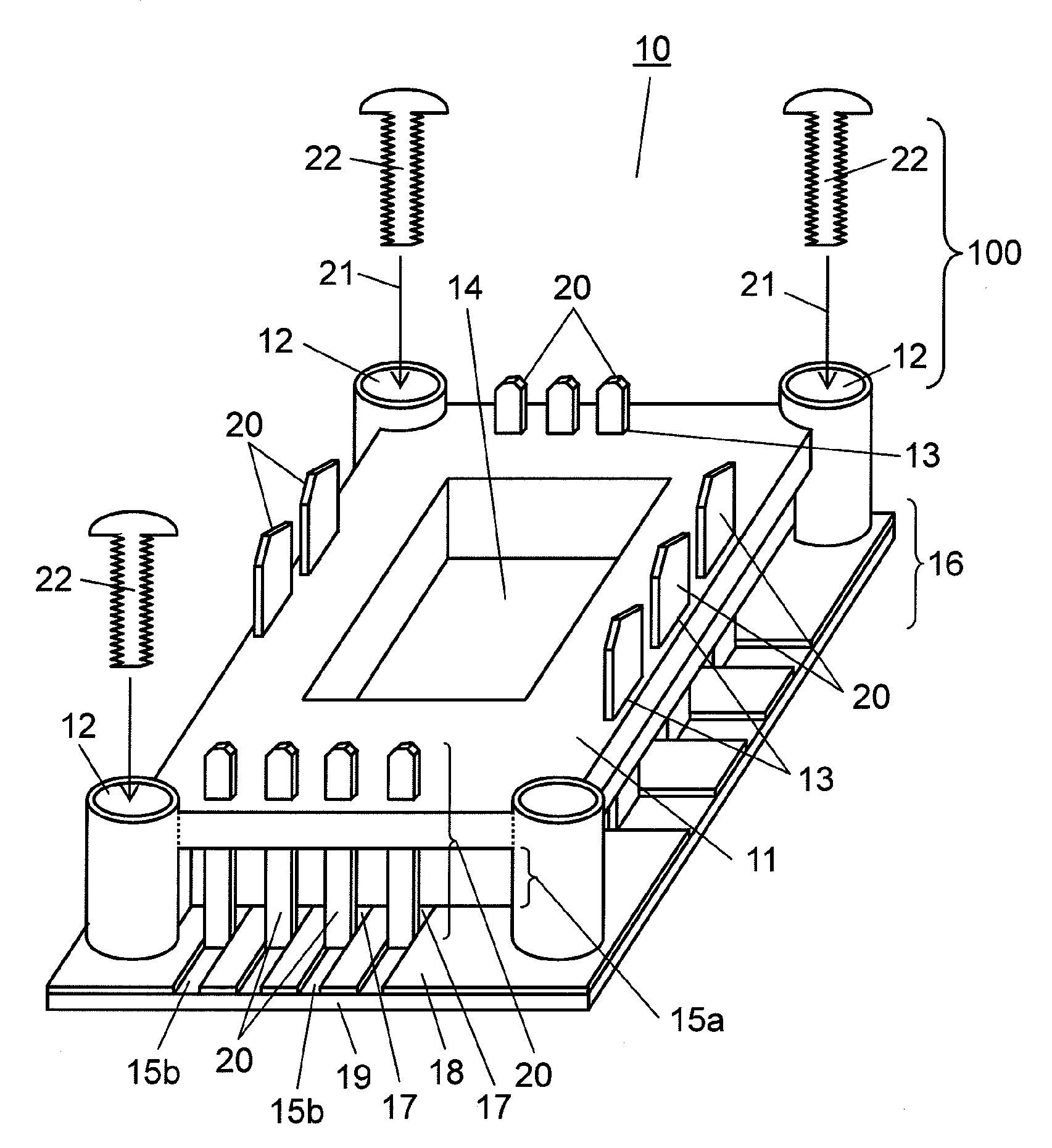
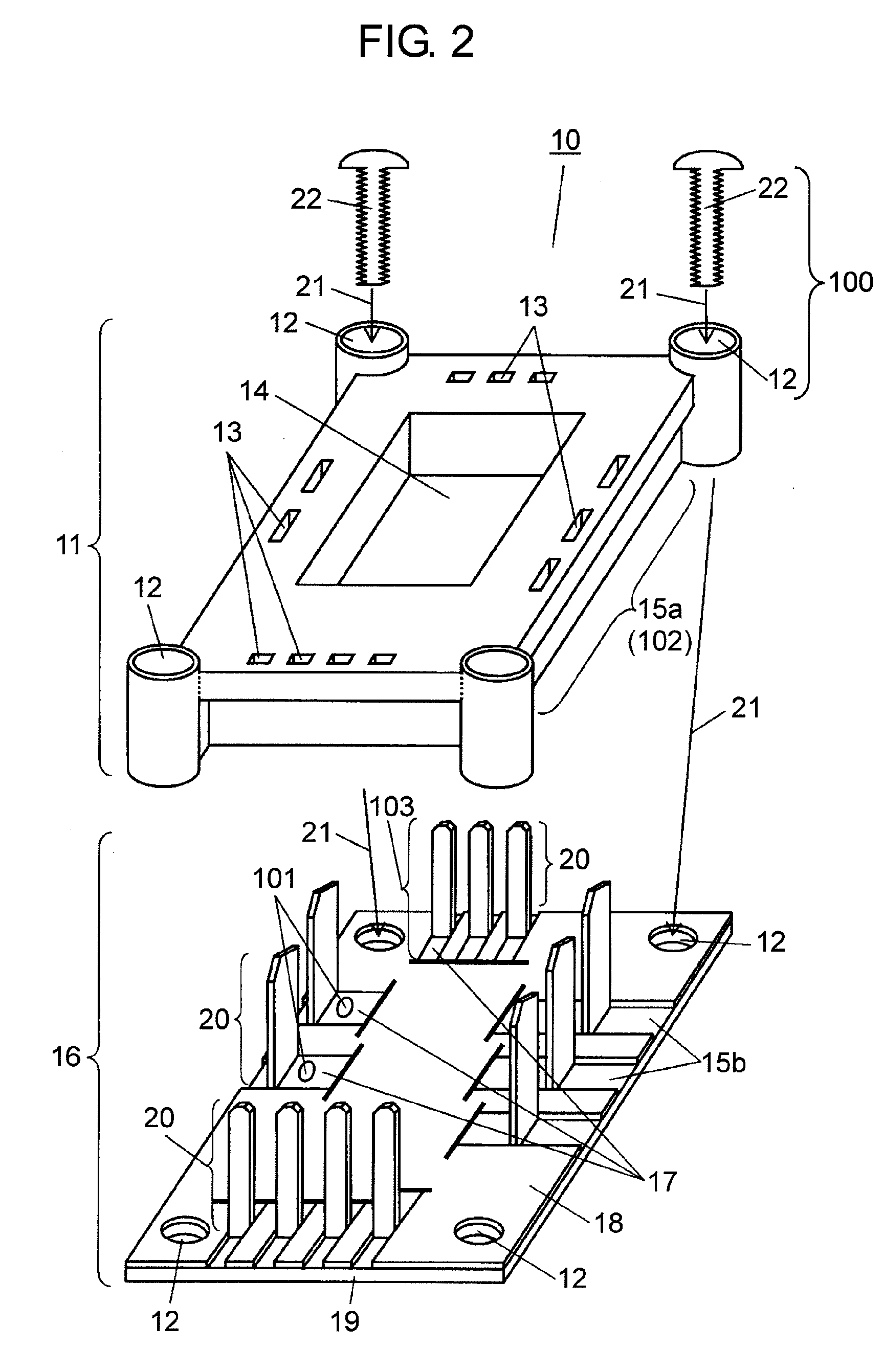
[0116]FIG. 1 is a perspective view showing an example of a resin structure employed to increase strengths of connection wirings of a heat dissipation structure substrate. In FIG. 1, heat dissipation structure board 10 is configured to include resin structure 11, attachment holes 12, wiring holes 13, opening 14, concave parts 15a and 15b, heat dissipation board 16, lead frames 17, heat transfer layer 18, metal plate 19, connection wirings 20 and screws 22.

[0117]Wiring holes 13 provided in resin structure 11 correspond to holes through which connection wirings 20 (connection wirings 20 may be a terminal part for connection to an external circuit or the like) formed in heat dissipation board 16 are penetrated (or, instead of being penetrated through, connection wirings 20 may be inserted, guided or fixed into...

second embodiment

[0157]An example of a method of manufacturing heat dissipation board 16 or heat dissipation structure board 10 described in the first embodiment will be described as a second embodiment with reference to FIGS. 3A, 3B, 4A and 4B.

[0158]Both FIGS. 3A and 3B are cross-sectional views describing an example of a method of manufacturing heat dissipation board 16.

[0159]First, as show in FIG. 3A, heat transfer resin 23 is set on metal plate 19 and lead frames 17 worked into a predetermined pattern shape are set on heat transfer resin 23. As indicated by arrow 21, these heat transfer resin 23 and lead frames 17 are integrated by being heated and pressed using a die and a press (both of which are not shown). Further, heat transfer resin 23 is hardened, thus providing heat transfer layer 18.

[0160]FIG. 3B is a cross-sectional view showing a state after hardening heat transfer resin 23 into heat transfer layer 18. As shown in FIG. 3B, a part of or more than a part of each lead frame 17 that const...

third embodiment

[0174]Members used for heat dissipation board 16, heat dissipation structure board 10 or the like will be described as a third embodiment.

[0175]As each of lead frames 17, a member made of such a material having high heat conductivity as copper or aluminum is preferably used. A thickness of each lead frame 17 is preferably not less than 0.2 mm (more preferably, not less than 0.3 mm). If the thickness of each lead frame 17 is less than 0.2 mm, there is a probability that a strength of each connection wiring 20 falls and connection wiring 20 is bent or deformed during operation.

[0176]Furthermore, the thickness of each lead frame 17 is preferably not more than 10.0 mm (more preferably, not more than 5.0 mm). If the thickness of each lead frame 17 exceeds 10.0 mm, the thickness may possibly influence formation of each connection wiring 20 into a fine pattern.

[0177]If thick lead frame 17 (at the thickness, for example, not less than 0.2 mm or preferably not less than 0.3 mm) is used while...


PUM


Abstract

The present invention relates to a heat dissipation structure board and a module using this heat dissipation structure used for purpose required of high reliability such as a hybrid vehicle or an electric vehicle and to a method of manufacturing the heat dissipation structure. A resin structure is disposed on a lead frame constituting a heat dissipation board and an odd-shaped electronic component or the like mounted on this lead frame or the like to cover up the lead frame and the odd-shaped electronic component or the like, and this resin structure is fixed to a metal plate, a chassis of a device and the like to constitute the heat dissipation structure board as a whole, whereby fixing strengths of fixing the lead frame and the odd-shaped electronic component or the like, a bonding strength at an interface between the lead frame and the heat transfer layer and the like can be reinforced.

Description

TECHNICAL FIELD[0001]The present invention relates to a heat dissipation structure board used in a hybrid vehicle such as a mild hybrid vehicle, an electric vehicle or an industrial device, a module using the heat dissipation structure board and a method of manufacturing the heat dissipation structure board.BACKGROUND ART[0002]Recently, attention has been paid to a hybrid vehicle or a variety of industrial devices realizing low power consumption by accumulating regenerative electric power during braking or the like in an electric double layer capacitor or the like.[0003]Such a device requires a circuit module dealing with high current such as a DC / DC converter (which converts a DC input into a DC output) controlling high current exceeding 100 A with high accuracy. It is necessary to mount a power semiconductor and the like used in this module on a heat dissipation board that can deal with heat dissipation and high current.[0004]As a heat dissipation board of this type, there is know...

Claims


Application Information

Patent Timeline
IPC IPC(8): H05K7/20B21D53/02
CPCH01L23/053Y10T29/4935H01L23/49861H01L23/645H01L25/162H01L2023/4025H01L2924/19105H05K1/0201H05K7/1432H01L2224/45124H01L23/3735H05K7/209H01L2224/73265H01L2224/48091H01L2924/00014H01L2924/00H05K7/14329
Inventor OHNISHI, TOHRUKOUNO, HITOSHITANIGUCHI, TOSHIYUKINAKASHIMA, KOJINAKATA, TOSHIYUKIIMANISHI, TSUNETSUGUNAKAO, KEIICHI
Owner PANASONIC CORP
Why Eureka
Try Eureka